LQ-670 Service Manual
Rev. A
A-3
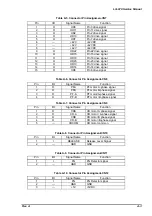
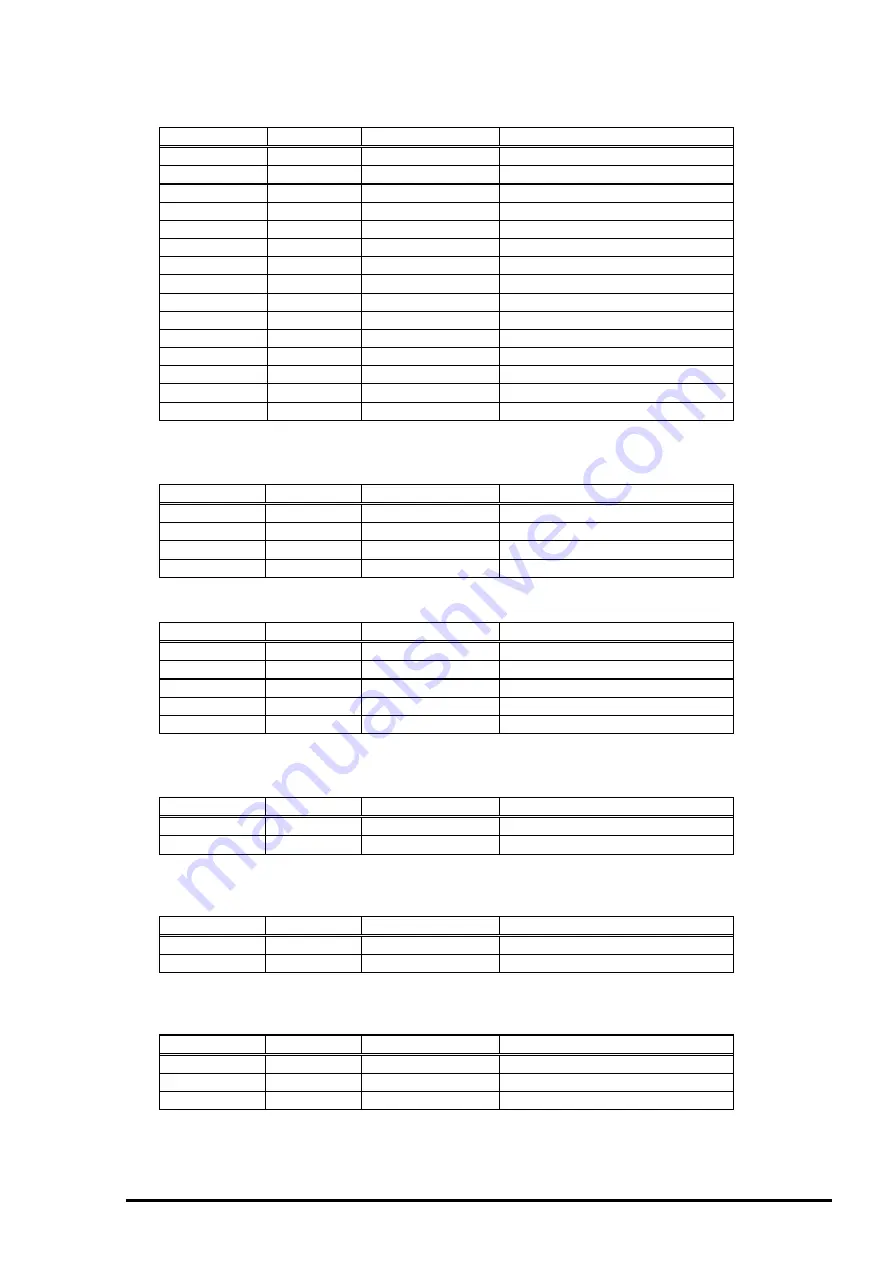
Pin
I/O
Signal Name
Function
1
O
HD3
Pin 3 drive signal
2
O
HD11
Pin 11 drive signal
3
O
HD2
Pin 2 drive signal
4
O
HD19
Pin 19 drive signal
5
O
HD7
Pin 7 drive signal
6
---
+42V
+42VDC
7
---
+42V
+42VDC
8
---
+42V
+42VDC
9
O
HD22
Pin 22 drive signal
10
O
HD15
Pin 15 drive signal
11
O
HD18
Pin 18 drive signal
12
O
HD23
Pin 23 drive signal
13
O
HD10
Pin 10 drive signal
14
O
HD14
Pin 14 drive signal
15
O
HD6
Pin 6 drive signal
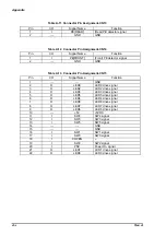
Pin
I/O
Signal Name
Function
1
O
PFA
PF motor A -phase signal
2
O
PFB
PF motor B-phase signal
3
O
PF-A
PF motor/A-phase signal
4
O
PF-B
PF motor / B-phase signal
Pin
I/O
Signal Name
Function
1
O
CRA
CR motor A phase signal
2
O
CR-A
CR motor / A-phase signal
3
O
CRB
CR motor B phase signal
4
O
CR-B
CR motor /B-phase signal
5
---
CRCOM
CR motor common
Pin
I/O
Signal Name
Function
1
I
RELEASE
Release Lever Signal
2
---
GND
GND
Pin
I/O
Signal Name
Function
1
I
PG
PG Detector signal
2
---
GND
GND
Pin
I/O
Signal Name
Function
1
I
PG
PG Detector signal
2
---
GND
GND
3
---
+5V
+5VDC
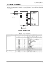
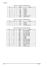
Table A-5. Connector Pin Assignmen-CN7
Table A-6. Connector Pin Assignment-CN8
Table A-7. Connector Pin Assignment-CN9
Table A-8. Connector Pin Assignment-CN10
Table A-9. Connector Pin Assignment-CN11
Table A-10. Connector Pin Assingment-CN12
Summary of Contents for LQ 670 - B/W Dot-matrix Printer
Page 1: ...EPSON IMPACT DOT MATRIX PRINTER EPSON LQ 670 SERVICE MANUAL SEIKO EPSON CORPORATION 4007875 ...
Page 5: ...v REVISION SHEET Revision Issued Data Contents Rev A May 28 1997 First issue ...
Page 114: ...Chapter 6 Maintenance 6 1 Preventive Maintenance 6 1 ...
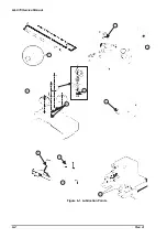
Page 116: ...LQ 670 Service Manual Rev A 6 2 Figure 6 1 Lubrication Points ...
Page 122: ...LQ 670 Service Manual Rev A A 5 A 2 Circuit Diagram Figure A 2 C214Main Board Circuit Diagram ...
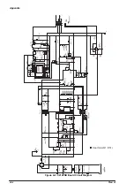
Page 123: ...Appendix Rev A A 6 Heat Sink Q1 D51 Figure A 3 C214PSB Board Circuit Diagram ...
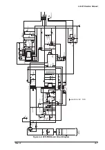
Page 124: ...LQ 670 Service Manual Rev A A 7 Heat Sink Q1 D51 Figure A 4 C214PSE Board Circuit Diagram ...
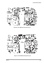
Page 125: ...Appendix Rev A A 8 A 3 Component Layout Figure A 5 C214 Main Board Component Layout ...
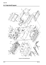
Page 127: ...Appendix Rev A A 10 A 4 Exploded Diagram Figure A 8 Exploded Diagram ...
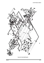
Page 128: ...LQ 670 Service Manual Rev A A 11 Figure A 9 Exploded Diagram ...
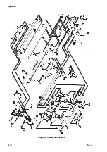
Page 129: ...Appendix Rev A A 12 Figure A 10 Exploded Diagram ...
Page 135: ...EPSON SEIKO EPSON CORPORATION ...

