LQ-670 Service Manual
Rev. A
A-15
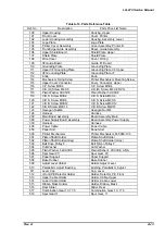
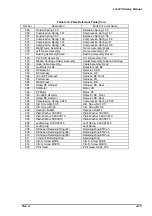
Ref. No
Description
Parts Price List Name
568
Tension Spring 14.5
Extension Spring, 14.5
569
Compression Spring 1.47
Compression Spring, 1.47
570
Tension Spring 0.55
Extension Spring, 0.55
571
Compression Spring 1.96
Compression Spring, 1.96
572
Compression Spring 1.47
Compression Spring,1.47
573
Compression Spring 1.96
Compression Spring, 1.96
575
Right Frame Assembly
Frame Assembly, Right
576
Left Frame Assembly
Frame Assembly, Left
577
Bushing Assembly Driven
Bushing Assembly, Driven
578
PW P.C.B Assembly
P.C.B Assembly, PW
579
Ribbon Cartridge Holder Assembly
Holder Assembly, Ribbon Cartridge
580
Head Cable Assembly
Cable Assembly, Head
581
Leaf Detector B2
Detector Leaf; B2
582
HP Detector
Detector, HP;D
583
HP Harness
Harness, HP
584
(Front) PF Harness
Harness, PE Front
585
PG Harness
Harness, PG
586
RE Harness
Harness, RE
587
(Rear) PE Harness
Harness, PE, Rear
588
CR Motor
Motor, CR
589
PF Motor
Motor, PF
590
(Front)PE Detector
Detector, PE, Front
591
(Rear) PE Detector
Detector, PE, Rear
592
Compression Spring 0.049
Compression Spring, 0.049
600
C.B. Screw M2.5X5
C.B. Screw M2.5X5
601
C.B. Screw M3X6
C.B. Screw M3X6
602
Hexagon Nut M4
Hexagon Nut M4
603
Plain Washer 3X0.5X8
Plain Washer 3X0.5X8
604
Plain Washer 5.2X0.3X10
Plain Washer 5.2X0.3X10
605
Plain Washer 8X0.5X15
Plain Washer 8X0.5X15
606
Leaf Spring 8.2X0.25X15
Leaf Spring 8.2X0.25X15
607
Leaf Spring
Leaf Spring
608
E-Shaped Retaining Ring (#3)
Retaining Ring ETWJ-3
609
E-Shaped Retaining Ring (#4)
Retaining Ring ETWJ-4
610
E-Shaped Retaining Ring (#6)
Retaining Ring ETWJ-6
611
Crescent Retaining Ring
Retaining Ring
612
C.B.S. Screw M3X6
C.B.S. Screw M3X6
613
C.B.S. Screw M3X10
C.B.S. Screw M3X10
650
Print Head
Print Head, DH24-0C0
Table A-16. Parts Reference Table (Con.)
Summary of Contents for LQ 670 - B/W Dot-matrix Printer
Page 1: ...EPSON IMPACT DOT MATRIX PRINTER EPSON LQ 670 SERVICE MANUAL SEIKO EPSON CORPORATION 4007875 ...
Page 5: ...v REVISION SHEET Revision Issued Data Contents Rev A May 28 1997 First issue ...
Page 114: ...Chapter 6 Maintenance 6 1 Preventive Maintenance 6 1 ...
Page 116: ...LQ 670 Service Manual Rev A 6 2 Figure 6 1 Lubrication Points ...
Page 122: ...LQ 670 Service Manual Rev A A 5 A 2 Circuit Diagram Figure A 2 C214Main Board Circuit Diagram ...
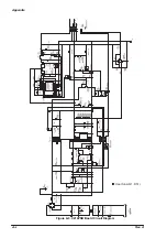
Page 123: ...Appendix Rev A A 6 Heat Sink Q1 D51 Figure A 3 C214PSB Board Circuit Diagram ...
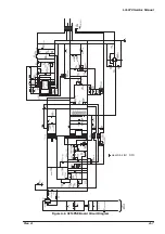
Page 124: ...LQ 670 Service Manual Rev A A 7 Heat Sink Q1 D51 Figure A 4 C214PSE Board Circuit Diagram ...
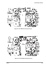
Page 125: ...Appendix Rev A A 8 A 3 Component Layout Figure A 5 C214 Main Board Component Layout ...
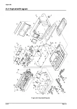
Page 127: ...Appendix Rev A A 10 A 4 Exploded Diagram Figure A 8 Exploded Diagram ...
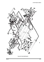
Page 128: ...LQ 670 Service Manual Rev A A 11 Figure A 9 Exploded Diagram ...
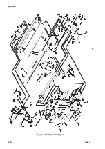
Page 129: ...Appendix Rev A A 12 Figure A 10 Exploded Diagram ...
Page 135: ...EPSON SEIKO EPSON CORPORATION ...

