LQ-670 Service Manual
Rev. A
1-8
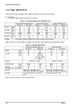
Continuous paper (Single sheet and Multi part)
Rear Entry (Tractor)
Minimum
Maximum
Width
(inch)
4
12
(mm)
101.6
304.8
Length(one page)
(inch)
4
22
(mm)
101.6
558.8
Copies
1 or 4 copies
Total thickness
(inch)
0.0025
0.015
(mm)
0.065
0.39
Weight
(g/m
2
)
52
82
(not multi part)
(lb)
14
22
Weight
(g/m
2
)
40
58
(one sheet of multi part) (lb)
12
15
Quality
Plain paper, Reclaimed paper
Carbonless multi part paper
Jointing
Point glue or paper staple(both side)
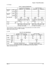
Continuous paper with Labels
Rear Entry (Tractor)
Minimum
Maximum
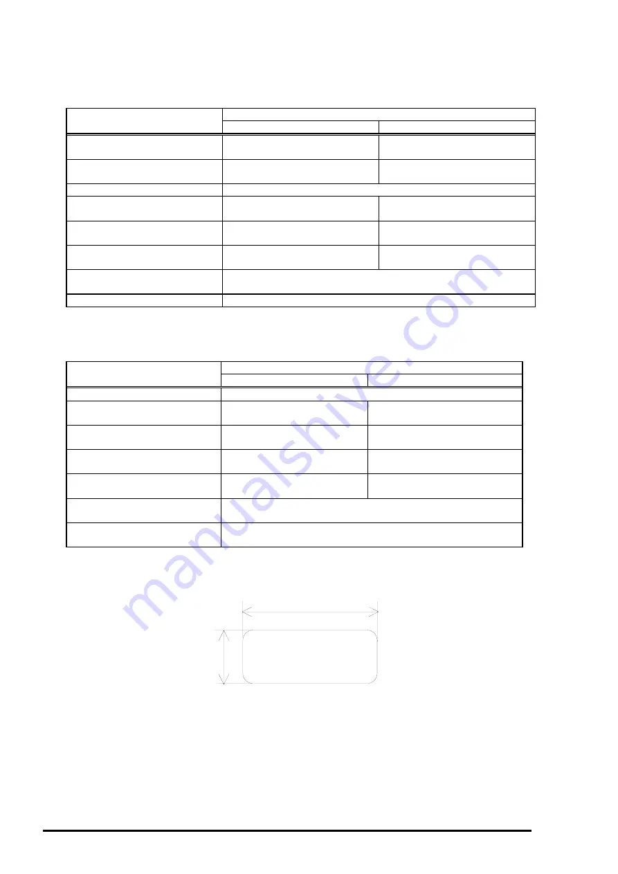
Label size
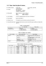
See the figure below.
Base sheet width
(inch)
4
12
(mm)
101.6
304.8
Base sheet length
(inch)
4
22
(one page)
(mm)
101.6
558.8
Base sheet
(inch)
0.0028
0.0035
Thickness
(mm)
0.07
0.09
Total thickness
(inch)
0.0063
0.0075
0.16
0.19
Label weight
(g/m
2
)
68
(lb)
17
Quality
A VERY CONTINUOUS FORM LABELS, A VERY MINI-LINE
LABELS or the same quality labels
Note)
: Printing on label is available only under the normal temperature and humidity conditions.
Note):
The base sheet of labels must be continuous paper.
Table 1-11. Continuous Paper (Single Sheet and Multi Part)
Table 1-12. Continuous Paper with Labels
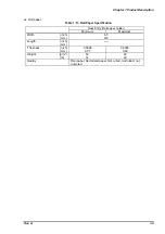
2.5 inch (63.5mm) min.
15/16 inch
(23.8mm)
min.
Label
R 0.1 inch(2.5mm) min.
Figure 1-3. Label Size
Summary of Contents for LQ 670 - B/W Dot-matrix Printer
Page 1: ...EPSON IMPACT DOT MATRIX PRINTER EPSON LQ 670 SERVICE MANUAL SEIKO EPSON CORPORATION 4007875 ...
Page 5: ...v REVISION SHEET Revision Issued Data Contents Rev A May 28 1997 First issue ...
Page 114: ...Chapter 6 Maintenance 6 1 Preventive Maintenance 6 1 ...
Page 116: ...LQ 670 Service Manual Rev A 6 2 Figure 6 1 Lubrication Points ...
Page 122: ...LQ 670 Service Manual Rev A A 5 A 2 Circuit Diagram Figure A 2 C214Main Board Circuit Diagram ...
Page 123: ...Appendix Rev A A 6 Heat Sink Q1 D51 Figure A 3 C214PSB Board Circuit Diagram ...
Page 124: ...LQ 670 Service Manual Rev A A 7 Heat Sink Q1 D51 Figure A 4 C214PSE Board Circuit Diagram ...
Page 125: ...Appendix Rev A A 8 A 3 Component Layout Figure A 5 C214 Main Board Component Layout ...
Page 127: ...Appendix Rev A A 10 A 4 Exploded Diagram Figure A 8 Exploded Diagram ...
Page 128: ...LQ 670 Service Manual Rev A A 11 Figure A 9 Exploded Diagram ...
Page 129: ...Appendix Rev A A 12 Figure A 10 Exploded Diagram ...
Page 135: ...EPSON SEIKO EPSON CORPORATION ...


