LQ-670 Service Manual
Rev. A
1-14
1.2.6 Ribbon Cartridge
Type
: Fabric
Color
: Black
Ribbon life
: 2 million characters (LQ 10cpi, 48 dots/character)
Dimensions
:120.5mm(W) x 101.5mm(D) x 23.5mm(H)
1.2.7 Input data buffer
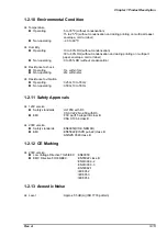
0 Kbyte or 64 Kbyte*
Note*)
: Depends on default settings.
1.2.8 Electrical Specification
120V version
Rated voltage
: AC120V
Input voltage range
: AC103.5 to 132V
Rated frequency range
: 50 to 60 Hz
Input frequency range
: 49.5 to 60.5 Hz
Rated current
: 0.7A(max.2.2A)
Power consumption
: Approx.30W (ISO/IEC10561 Letter pattern)
Energy Star Compliant
Insulation resistance
: 10 M
Ω
min.(between AC line and chassis, DC 500V)
Dielectric strength
: AC1000 Vrms. 1min.or
AC1200 Vrms. 1 sec.(between AC line and chassis)
230 V version
Rated voltage
: AC220 to 240V
Input voltage range
: AC198 to 264V
Rated frequency range
: 50 to 60Hz
Input frequency range
: 49.5 to 60.5Hz
Rated current
: 0.4A (max.1.1A)
Power consumption
: Approx.30W (ISO/IEC10561 Letter pattern)
Energy Star Compliant
Insulation resistance
: 10M
Ω
min. (between AC line and chassis, DC 500V)
Dielectric strength
: AC1500 Vrms. 1min.(between AC line and chassis)
1.2.9 Reliability
Total print volume
: 6.5 million lines (except print head)
(MTBF)
: 5000 POH
Print head life
: 200 million strokes/wire
Ribbon life
: 2 million characters
Summary of Contents for LQ 670 - B/W Dot-matrix Printer
Page 1: ...EPSON IMPACT DOT MATRIX PRINTER EPSON LQ 670 SERVICE MANUAL SEIKO EPSON CORPORATION 4007875 ...
Page 5: ...v REVISION SHEET Revision Issued Data Contents Rev A May 28 1997 First issue ...
Page 114: ...Chapter 6 Maintenance 6 1 Preventive Maintenance 6 1 ...
Page 116: ...LQ 670 Service Manual Rev A 6 2 Figure 6 1 Lubrication Points ...
Page 122: ...LQ 670 Service Manual Rev A A 5 A 2 Circuit Diagram Figure A 2 C214Main Board Circuit Diagram ...
Page 123: ...Appendix Rev A A 6 Heat Sink Q1 D51 Figure A 3 C214PSB Board Circuit Diagram ...
Page 124: ...LQ 670 Service Manual Rev A A 7 Heat Sink Q1 D51 Figure A 4 C214PSE Board Circuit Diagram ...
Page 125: ...Appendix Rev A A 8 A 3 Component Layout Figure A 5 C214 Main Board Component Layout ...
Page 127: ...Appendix Rev A A 10 A 4 Exploded Diagram Figure A 8 Exploded Diagram ...
Page 128: ...LQ 670 Service Manual Rev A A 11 Figure A 9 Exploded Diagram ...
Page 129: ...Appendix Rev A A 12 Figure A 10 Exploded Diagram ...
Page 135: ...EPSON SEIKO EPSON CORPORATION ...


