Chapter 3 Disassembly and Assembly
Rev. A
3-7
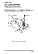
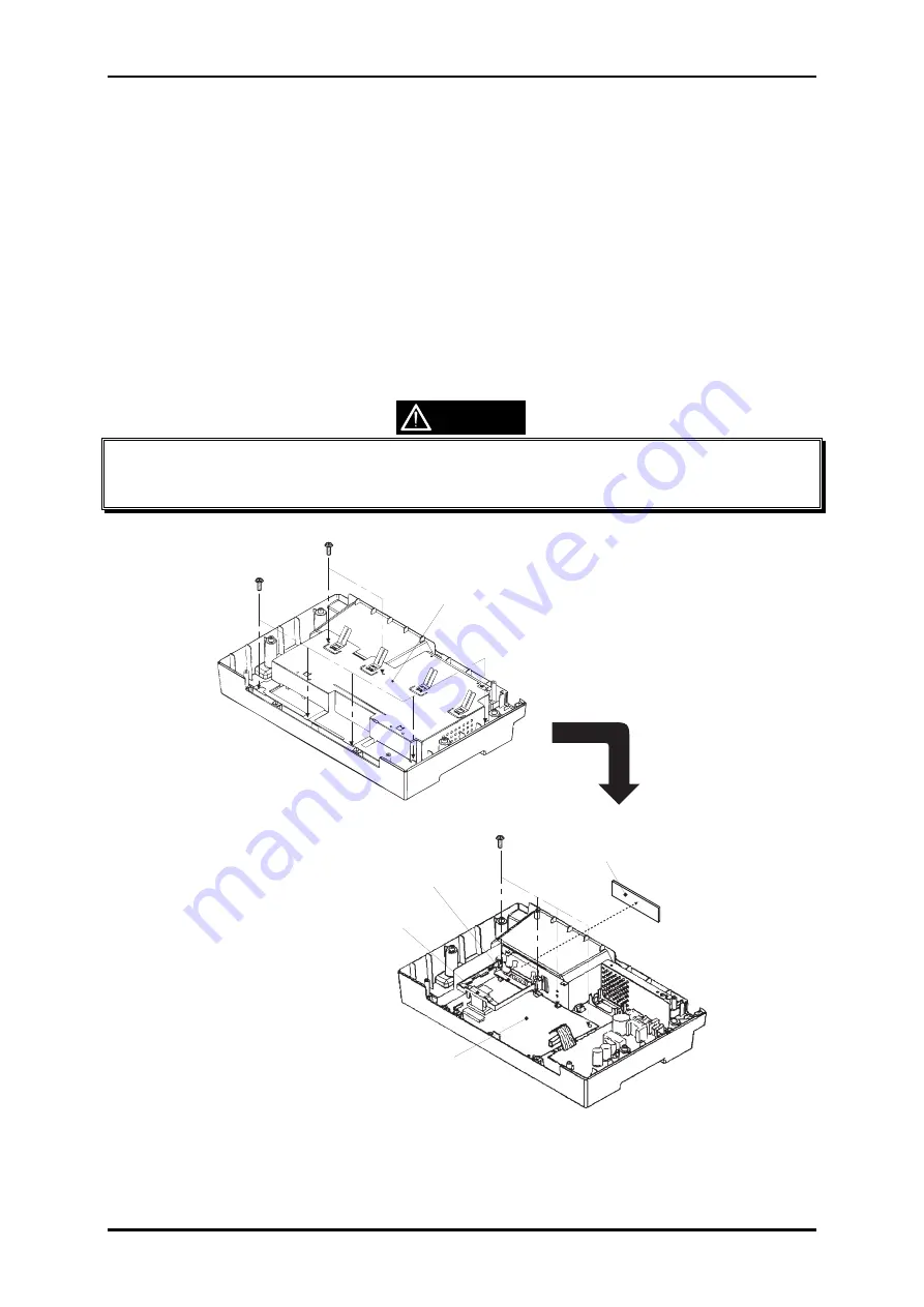
3.2.3 C214 MAIN Board Removal
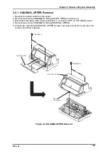
1. Remove [HOUSING, UPPER] (See Section 3.2.1)
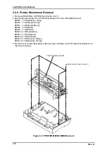
2. Remove Printer Mechanism (See Section 3.2.2)
3. Remove seven screws (5: CBB/M3x12, 2: CBS/M3x4) fixing the shield plate, and remove
the shield plate.
4. Remove two screws (CBS/M3x12) fixing [COVER, CONNECTOR, UPPER], and remove
[COVER, CONNECTOR, UPPER].
5. Disconnect the cable of power supply unit from a connector CN3 on C214 MAIN board.
6. Remove four screws (CBB/M3x12) fixing C214 MAIN board, and remove C214 MAIN
board together with [GROUND PLATE, I/F, UPPER].
7. Remove [GROUND PLATE, I/F, UPPER] from C214 MAIN board.
8. Remove [GUIDE, I/F BOARD;B] from C214 MAIN board by unhooking two tabs.
9. Remove two screws (CP/M3x12) fixing [GROUND PLATE, I/F] and remove it from C214
MAIN board.
Be careful with the edges of the shield plate, as they are very sharp.
Make sure to match a RED marking on the cable of the motors, to pin 1 of
connector on C214 MAIN board when you re-connect them.
CAUTION
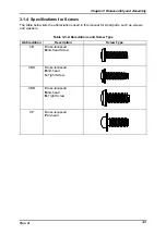
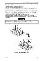
CBS (M3x4)
CBB (M3x12)
SHIELD PLATE
C214 MAIN BOARD
GUIDE, I/F BOARD; B
GROUND PLATE, I/F, UPPER
COVER, CONNECTOR, UPPER
Figure 3-4. C214 MAIN Board Removal
Summary of Contents for LQ 670 - B/W Dot-matrix Printer
Page 1: ...EPSON IMPACT DOT MATRIX PRINTER EPSON LQ 670 SERVICE MANUAL SEIKO EPSON CORPORATION 4007875 ...
Page 5: ...v REVISION SHEET Revision Issued Data Contents Rev A May 28 1997 First issue ...
Page 114: ...Chapter 6 Maintenance 6 1 Preventive Maintenance 6 1 ...
Page 116: ...LQ 670 Service Manual Rev A 6 2 Figure 6 1 Lubrication Points ...
Page 122: ...LQ 670 Service Manual Rev A A 5 A 2 Circuit Diagram Figure A 2 C214Main Board Circuit Diagram ...
Page 123: ...Appendix Rev A A 6 Heat Sink Q1 D51 Figure A 3 C214PSB Board Circuit Diagram ...
Page 124: ...LQ 670 Service Manual Rev A A 7 Heat Sink Q1 D51 Figure A 4 C214PSE Board Circuit Diagram ...
Page 125: ...Appendix Rev A A 8 A 3 Component Layout Figure A 5 C214 Main Board Component Layout ...
Page 127: ...Appendix Rev A A 10 A 4 Exploded Diagram Figure A 8 Exploded Diagram ...
Page 128: ...LQ 670 Service Manual Rev A A 11 Figure A 9 Exploded Diagram ...
Page 129: ...Appendix Rev A A 12 Figure A 10 Exploded Diagram ...
Page 135: ...EPSON SEIKO EPSON CORPORATION ...

