Chapter 3 Disassembly and Assembly
Rev. A
3-19
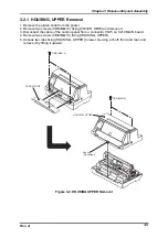
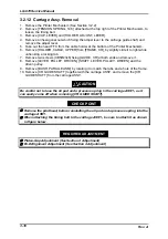
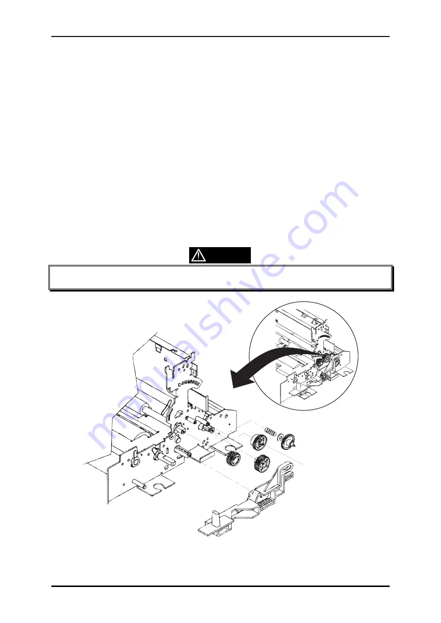
3.2.13 PAPER GUIDE Removal
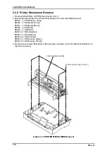
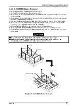
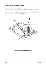
1. Remove the Printer Mechanism. (See Section 3.2.2)
2. Remove the paper exit ASSY. (See Section 3.2.8)
3. Remove the carriage ASSY. (See Section 3.2.12)
4. Remove the CR motor cover from [FRAME, CR] and [MOTOR, CR].
5. Remove [DETECTOR, HP] and [DETECTOR, PG].
6. Remove [GEAR, 20] from [FRAME ASSY., RIGHT] by unhooking a tab.
7. Remove four screws (CBS/M3x6) fixing [FRAME,CR] to the frame assembly RIGHT and
LEFT, and remove [FRAME, CR].
8. Remove [GEAR, 14] and [COMBINATION GEAR, 16, 16] from the both ends of
[ROLLER, PF, DRIVE].
9. Remove an E-shaped retaining ring (#2) from the left end of [ROLLER, PF, DRIVE].
10. Remove the shaft holder at the both end of [ROLLER, PF, DRIVE].
11. Remove a screw (CBS/M3x6) fixing the CR motor frame to [FRAME ASSY., LEFT].
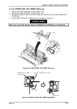
12. Take out [DETECTOR, PF, FRONT] from the paper guide.
13. Slide [ROLLER, PF, DRIVE] to right once to dismount the one end of the shaft from
[FRAME ASSY., LEFT], then slide it to left to remove it.
14. Remove an E-shaped retaining ring (#4) fixing [COMBINATION GEAR, 8, 30], and
remove [COMBINATION GEAR, 8, 30] and [GEAR, 36] from [FRAME ASSY., LEFT].
15. Remove four screws (CBS/M3x6) fixing the paper guide and remove it.
Be careful not to damage the actuator of [DETECTOR, PE, REAR] while removing
[ROLLER, PF, DRIVE].
CAUTION
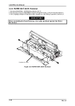
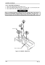
GEAR, 20
(WHITE)
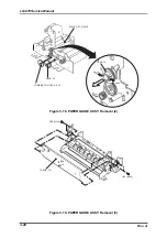
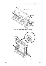
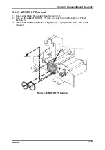
Figure 3-17. PAPER GUIDE ASSY. Removal (1)
Summary of Contents for LQ 670 - B/W Dot-matrix Printer
Page 1: ...EPSON IMPACT DOT MATRIX PRINTER EPSON LQ 670 SERVICE MANUAL SEIKO EPSON CORPORATION 4007875 ...
Page 5: ...v REVISION SHEET Revision Issued Data Contents Rev A May 28 1997 First issue ...
Page 114: ...Chapter 6 Maintenance 6 1 Preventive Maintenance 6 1 ...
Page 116: ...LQ 670 Service Manual Rev A 6 2 Figure 6 1 Lubrication Points ...
Page 122: ...LQ 670 Service Manual Rev A A 5 A 2 Circuit Diagram Figure A 2 C214Main Board Circuit Diagram ...
Page 123: ...Appendix Rev A A 6 Heat Sink Q1 D51 Figure A 3 C214PSB Board Circuit Diagram ...
Page 124: ...LQ 670 Service Manual Rev A A 7 Heat Sink Q1 D51 Figure A 4 C214PSE Board Circuit Diagram ...
Page 125: ...Appendix Rev A A 8 A 3 Component Layout Figure A 5 C214 Main Board Component Layout ...
Page 127: ...Appendix Rev A A 10 A 4 Exploded Diagram Figure A 8 Exploded Diagram ...
Page 128: ...LQ 670 Service Manual Rev A A 11 Figure A 9 Exploded Diagram ...
Page 129: ...Appendix Rev A A 12 Figure A 10 Exploded Diagram ...
Page 135: ...EPSON SEIKO EPSON CORPORATION ...

