LQ-670 Service Manual
Rev. A
5-1
5.1 Overview
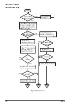
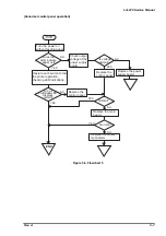
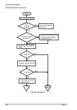
This chapter contains flowcharts and checkpoint tables to help you troubleshoot the printer. Flowcharts let
you isolate a faulty unit based on abnormal symptoms. The checkpoint tables let you identify the faulty
part or unit by checking the values or ranges listed for each component.
The first step of repairing is the unit exchange. Servicemen need to find defective units and replace them.
After repairing, it is necessary to perform appropriate adjustments (Refer to Chapter 4 for Adjustment) and
Lubrication (Refer to Chapter 6 for Maintenance). The table below shows tools required for the
troubleshooting.
Name
Specification
Oscilloscope
Recommended more than 50MHz
Multimeter
Analog is OK, but Digital multimeter is recommended.
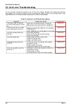
Also, this printer has self-diagnosis function which beeps when the printer detects error conditions.
Following table shows error conditions and buzzer sounds to indicate errors.
Indicator
Error Condition
Pause
Paper Out
Tear Off/
Bin
Condensed
Font
Buzzer
Paper out error
On
On
---
---
---
❍
X3
Paper Jam error
On
Blink
---
---
---
●
X5
Paper eject error
On
Blink
---
---
---
❍
X3
Head Hot
Blink
---
---
---
---
---
Fatal error
Blink
---
Note)
❍
indicates that the beep sounds for 100ms with an interval of 100ms.
●
indicates that the beep sounds for 500ms with an interval of 100ms.
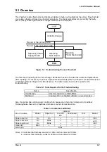
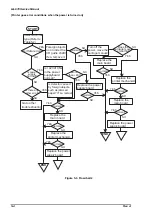
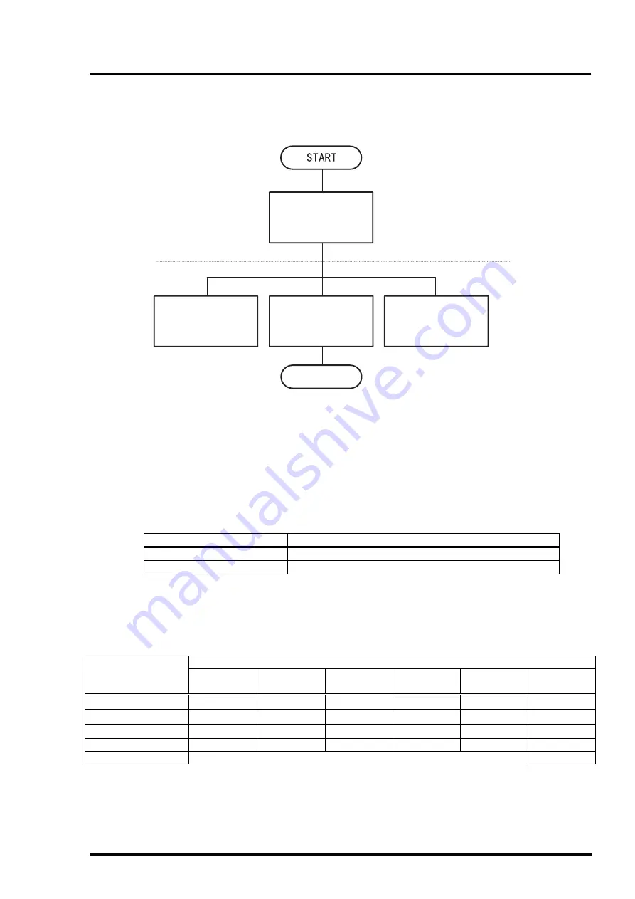
Units Exchange
Repair of the primary side
Repair of the secondary side
Repairing Power
Supply Board
Repairing
Main Board
Repairing
Printer Mechanism
END
Figure 5-1. Troubleshooting Process Flowchart
Table 5-1. Tools Required for the Troubleshooting
Table 5-2. Indicators and Buzzer
Summary of Contents for LQ 670 - B/W Dot-matrix Printer
Page 1: ...EPSON IMPACT DOT MATRIX PRINTER EPSON LQ 670 SERVICE MANUAL SEIKO EPSON CORPORATION 4007875 ...
Page 5: ...v REVISION SHEET Revision Issued Data Contents Rev A May 28 1997 First issue ...
Page 114: ...Chapter 6 Maintenance 6 1 Preventive Maintenance 6 1 ...
Page 116: ...LQ 670 Service Manual Rev A 6 2 Figure 6 1 Lubrication Points ...
Page 122: ...LQ 670 Service Manual Rev A A 5 A 2 Circuit Diagram Figure A 2 C214Main Board Circuit Diagram ...
Page 123: ...Appendix Rev A A 6 Heat Sink Q1 D51 Figure A 3 C214PSB Board Circuit Diagram ...
Page 124: ...LQ 670 Service Manual Rev A A 7 Heat Sink Q1 D51 Figure A 4 C214PSE Board Circuit Diagram ...
Page 125: ...Appendix Rev A A 8 A 3 Component Layout Figure A 5 C214 Main Board Component Layout ...
Page 127: ...Appendix Rev A A 10 A 4 Exploded Diagram Figure A 8 Exploded Diagram ...
Page 128: ...LQ 670 Service Manual Rev A A 11 Figure A 9 Exploded Diagram ...
Page 129: ...Appendix Rev A A 12 Figure A 10 Exploded Diagram ...
Page 135: ...EPSON SEIKO EPSON CORPORATION ...

