LQ-670 Service Manual
Rev. A
5-2
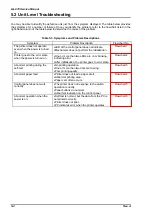
5.2 Unit Level Troubleshooting
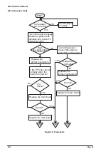
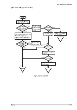
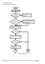
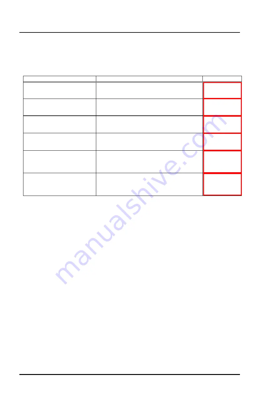
You may be able to identify the defective unit just from the symptom displayed. The table below provides
the symptoms for a number of failures. Once you identify the problem, refer to the flowchart listed in the
right-hand column of the table below to determine the cause of the problem.
Symptom
Problem Description
Flowchart No.
The printer does not operate
even when the power is turned
on.
•
LED of the control panel does not indicate.
•
Mechanism does not perform the initialization.
Printer goes to the error state
when the power is turned on.
•
One or more than two LEDs are on or blinking,
indicating error.
•
After initialization, the printer goes to error state.
Abnormal printing during the
self-test
•
No printing operation.
•
One or more than two dots are missing.
•
Poor printing quality.
Abnormal paper feed
•
Printer does not feed a paper at all.
•
Abnormal printing area.
•
Paper Jam often occurs.
Control panel does not work
correctly
•
The printer does not response to the switch
operation correctly.
•
Panel buttons do not work.
•
Abnormal indication on the control panel
Abnormal operation when the
power is on.
•
Self test is normal, but the data from the PC is
not printed correctly.
•
Printer does not print.
•
PC indicates error when the printer operates.
Table 5-3. Symptoms and Problem Descriptions
Summary of Contents for LQ 670 - B/W Dot-matrix Printer
Page 1: ...EPSON IMPACT DOT MATRIX PRINTER EPSON LQ 670 SERVICE MANUAL SEIKO EPSON CORPORATION 4007875 ...
Page 5: ...v REVISION SHEET Revision Issued Data Contents Rev A May 28 1997 First issue ...
Page 114: ...Chapter 6 Maintenance 6 1 Preventive Maintenance 6 1 ...
Page 116: ...LQ 670 Service Manual Rev A 6 2 Figure 6 1 Lubrication Points ...
Page 122: ...LQ 670 Service Manual Rev A A 5 A 2 Circuit Diagram Figure A 2 C214Main Board Circuit Diagram ...
Page 123: ...Appendix Rev A A 6 Heat Sink Q1 D51 Figure A 3 C214PSB Board Circuit Diagram ...
Page 124: ...LQ 670 Service Manual Rev A A 7 Heat Sink Q1 D51 Figure A 4 C214PSE Board Circuit Diagram ...
Page 125: ...Appendix Rev A A 8 A 3 Component Layout Figure A 5 C214 Main Board Component Layout ...
Page 127: ...Appendix Rev A A 10 A 4 Exploded Diagram Figure A 8 Exploded Diagram ...
Page 128: ...LQ 670 Service Manual Rev A A 11 Figure A 9 Exploded Diagram ...
Page 129: ...Appendix Rev A A 12 Figure A 10 Exploded Diagram ...
Page 135: ...EPSON SEIKO EPSON CORPORATION ...


