Maintenance 5. Arm #1
LS20 Rev.4
91
Joint #1
Reduction
Gear Unit
Installation
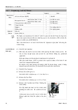
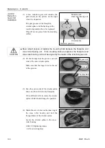
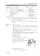
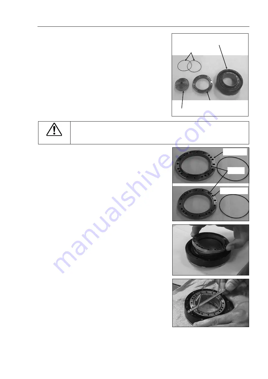
(1) A new reduction gear unit contains the
parts shown in the picture on the right
when it is unpacked.
The gear grooves of the flexspline,
circular spline, and the bearings of the
waveform generator have been greased.
Wipe off excess grease from the
mounting surface.
Flexspline and
Cross roller bearing unit
Circular spline
Waveform generator
O-ring
CAUTION
■
Never adjust (loosen or tighten) the mounting bolts between the flexspline and
cross roller bearing unit. If the mounting bolts are adjusted, the flexspline and
cross roller bearing unit must be aligned by the maker of the reduction gear unit.
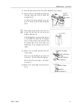
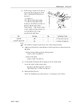
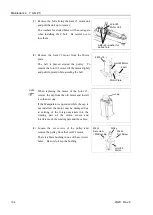
(2) Fit the O-rings into the grooves on both
sides of the new circular spline.
Make sure that the rings do not come out
of the grooves.
Convex side
Grooves
The other side
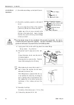
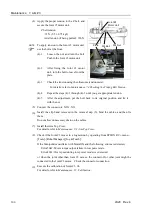
(3) Face the convex side of the circular spline
down, and then fit it into the flexspline.
(4) Match the screw holes on the inner ring
of the cross roller bearing unit and the
through holes of the circular spline.
Secure the circular spline to the cross
roller bearing. 4-M4×20
Tightening torque
: 4.0
N∙m (40.8 kgf∙cm)
Summary of Contents for LS20
Page 1: ...Rev 4 EM179R3533F SCARA ROBOT LS20 series MANIPULATOR MANUAL ...
Page 2: ...MANIPULATOR MANUAL LS20 series Rev 4 ...
Page 8: ...vi LS20 Rev 4 ...
Page 12: ...TABLE OF CONTENTS x LS20 Rev 4 ...
Page 14: ......
Page 29: ...Setup Operation 2 Specifications LS20 Rev 4 17 LS20 804S Standard Model ...
Page 31: ...Setup Operation 2 Specifications LS20 Rev 4 19 LS20 804C Cleanroom Model ...
Page 33: ...Setup Operation 2 Specifications LS20 Rev 4 21 LS20 A04S Standard Model ...
Page 35: ...Setup Operation 2 Specifications LS20 Rev 4 23 LS20 A04C Cleanroom Model ...
Page 72: ......
Page 92: ...Maintenance 4 Cable 80 LS20 Rev 4 4 2 Wiring Diagrams 4 2 1 Signal Cable ...
Page 176: ...Maintenance 14 Maintenance Parts List 164 LS20 Rev 4 ...


