Setup & Operation 3. Environments and Installation
LS20 Rev.4
37
3.6 Connecting the Cables
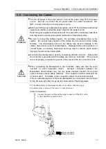
WARNING
■
To shut off power to the robot system, pull out the power plug from the power
source. Be sure to connect the AC power cable to a power receptacle. DO
NOT connect it directly to a factory power source.
■
Before performing any replacement procedure, turn OFF the Controller and related
equipment, and then pull out the power plug from the power source.
Performing any replacement procedure with the power ON is extremely hazardous
and may result in electric shock and/or malfunction of the robot system.
■
Be sure to connect the cables properly. Do not allow unnecessary strain on the
cables. (Do not put heavy objects on the cables. Do not bend or pull the cables
forcibly.) The unnecessary strain on the cables may result in damage to the
cables, disconnection, and/or contact failure. Damaged cables, disconnection, or
contact failure is extremely hazardous and may result in electric shock and/or
improper function of the robot system.
■
Grounding the manipulator is done by connecting with the controller. Ensure that
the controller is grounded and the cables are correctly connected. If the ground
wire is improperly connected to ground, it may result in the fire or electric shock.
CAUTION
■
When connecting the Manipulator to the Controller, make sure that the serial
numbers on each equipment match. Improper connection between the
Manipulator and Controller may not only cause improper function of the robot
system but also serious safety problems. The connection method varies with the
Controller used. For details on the connection, refer to the
Controller manual
.
If the G series Manipulator or E2 series Manipulator is connected to the Controller
for the PS series (ProSix), it may result in malfunction of the Manipulator.
For the Manipulator of Cleanroom-model, use it with an exhaust system.
For details, refer to
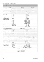
Setup & Operation: 2.4 Specifications.
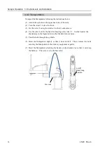
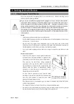
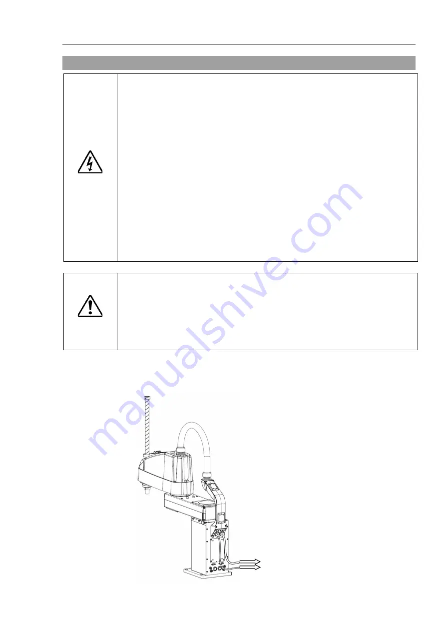
Cable Connections
Power connector
Signal connector
Connect the power cable and the signal connector of the M/C cable
to the Controller as shown below.
Summary of Contents for LS20
Page 1: ...Rev 4 EM179R3533F SCARA ROBOT LS20 series MANIPULATOR MANUAL ...
Page 2: ...MANIPULATOR MANUAL LS20 series Rev 4 ...
Page 8: ...vi LS20 Rev 4 ...
Page 12: ...TABLE OF CONTENTS x LS20 Rev 4 ...
Page 14: ......
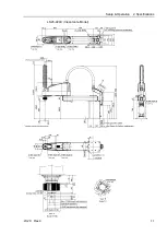
Page 29: ...Setup Operation 2 Specifications LS20 Rev 4 17 LS20 804S Standard Model ...
Page 31: ...Setup Operation 2 Specifications LS20 Rev 4 19 LS20 804C Cleanroom Model ...
Page 33: ...Setup Operation 2 Specifications LS20 Rev 4 21 LS20 A04S Standard Model ...
Page 35: ...Setup Operation 2 Specifications LS20 Rev 4 23 LS20 A04C Cleanroom Model ...
Page 72: ......
Page 92: ...Maintenance 4 Cable 80 LS20 Rev 4 4 2 Wiring Diagrams 4 2 1 Signal Cable ...
Page 176: ...Maintenance 14 Maintenance Parts List 164 LS20 Rev 4 ...

