LX-300+/1170
Revision C
Disassembly and Assembly
Disassembly and Assembly
82
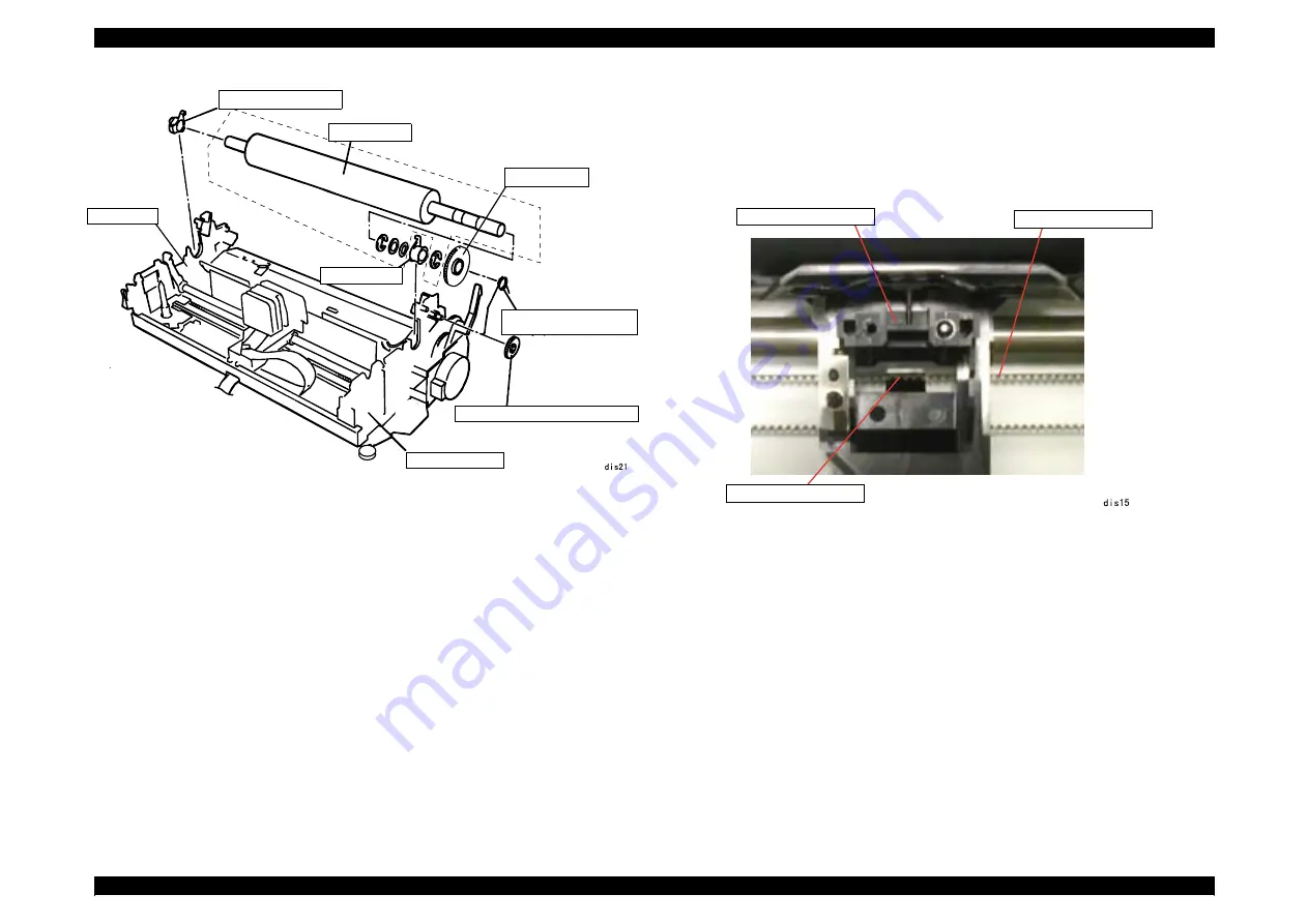
Figure4-13. Platen Removal
4.2.7.3 Carriage Unit Removal
1.
Remove the printer mechanism. (See 4.2.3 "Printer Mechanism Removal".)
2.
Remove the printhead. (See 4.2.1 "Printhead Removal".)
3.
Remove the timing belt from the carriage installation point.
Figure4-14. Timing Belt Removal
4.
Remove the CR shaft grounding plate from the base frame on the left side of the
printer.
Bushing, 11
Platen
Gear, 34
Platen grounding wire
Combination gear, 17.5, 27
Right frame
Left frame
Bushing, 11
Carriage Unit
Timing Belt
Installation Point
Summary of Contents for LX-1170
Page 8: ...C H A P T E R 1 PRODUCTDESCRIPTION ...
Page 44: ...C H A P T E R 2 OPERATINGPRINCIPLES ...
Page 60: ...C H A P T E R 3 TROUBLESHOOTING ...
Page 69: ...C H A P T E R 4 DISASSEMBLYANDASSEMBLY ...
Page 89: ...LX 300 1170 Revision C Disassembly and Assembly Disassembly and Assembly 89 ...
Page 90: ...C H A P T E R 5 ADJUSTMENT ...
Page 98: ...C H A P T E R 6 MAINTENANCE ...
Page 103: ...C H A P T E R 1 9 7 APPENDIX ...
Page 125: ......
Page 126: ......
Page 127: ......
Page 128: ......
Page 129: ......


