background image

EPSON TERM NAL PR NTER

LX-300

SERVICE MANUAL

EPSON

Summary of Contents for LX-300

Page 1: ... EPSON TERM NAL PR NTER LX 300 SERVICE MANUAL EPSON ...

Page 2: ... DO NOT CONNECT THE UNIT TO A POWER SOURCE UNTIL INSTRUCTED TO DO SO WHEN THE POWER SUPPLY CABLE MUST BE CONNECTED USE EXTREME CAUTION IN WORKING ON POWER SUPPLY AND OTHER ELECTRONIC COMPONENTS 1 REPAIRS ON EPSON PRODUCT SHOULD BE PERFORMED ONLY BY AN EPSON CERTIFIED REPAIR TECHNICIAN 2 MAKE CERTAIN THAT THE SOURCE VOLTAGE IS THE SAME AS THE RATED VOLT AGE LISTED ON THE SERIAL NUMBER RATING PLATE ...

Page 3: ...s of the pMter CHAPTER 2 OPERATING PRINCIPLES Describes the theory of printer operation CHAPTER 3 DISASSEMBLY AND ASSEMBLY Includes a step by step guide for product disassembly and assembly CHAPTER 4 ADJUSTMENTS Includes a step by step guide for adjustment CHAPTER 5 TROUBLESHOOTING Provides Epson approved techniques for adjustment CHAPTER 6 MAINTENANCE Describes preventive maintenance techniques a...

Page 4: ...REVISION SHEET Revision Issue Date Revision Page Rev A April 6 1994 1st issue 4 j v ...

Page 5: ...TABLE OF CONTENTS CHAPTER 1 CHAPTER 2 CHAPTER 3 CHAPTER 4 CHAPTER 5 CHAPTER 6 APPENDIX PRODUCT DESCRIPTION OPERATING PRINCIPLES DISASSEMBLY AND ASSEMBLY ADJUSTMENTS TROUBLESHOOTING MAINTENANCE vi ...

Page 6: ...9 1 3 INTERFACE SPECIFICATIONS 1 11 1 3 1 Parallel Interface Specifications 1 11 1 3 2 Serial InterfaceSpecifications 1 13 1 4 OPERATING INSTRUCTIONS 1 14 1 4 1 Control Panel Operation 1 14 1 4 2 Self test Function 1 15 1 4 3 Hexadecimal Dump Function 1 15 1 4 4 PrinterStatus Indication 1 15 1 4 5 Selected Font 1 15 1 4 6 Paper Position Adjustments 1 15 1 4 7 Printer Initialization 1 16 1 4 7 1 Ha...

Page 7: ...ications for Continuous Paper Single Sheet and Multi Part 1 4 Table 1 8 Specifications for Continuous Paper with a Label 1 5 Table l 9 Roil Paper Specifications 1 5 Table l 10 Electrical Specifications 1 8 Table 1 11 Table 1 12 Table 1 13 Table 1 14 Table 1 15 Table 1 16 Table 1 17 Table 1 18 Table 1 19 Table 1 20 Table 1 21 Table Table Table Table Table Table 22 23 24 25 26 27 Environmental Condi...

Page 8: ...ter size paper Optional color printing usinga color ribbon black magenta cyan yellow Detachable push and pull tractor Figure 1 1 shows an exterior view of the LX 300 and Table 1 1 lists the optional units available for the LX 300 Edge guties p perwppof s A Power lease YA r feed b A w Pfintercover A 5 Print head Sprocket unit Paper Jpport Troctof Figure 1 1 Exterior View of the LX 300 Table 1 1 Opt...

Page 9: ...1 2 1 Hardware Specifications Printing method Serial impact dot matrix Pin configuration 9 wires Pin diameter 0 29 mm Printing direction Figure 1 2 Pin Configuration Bidirectional with logic seeking for draft text with monochrome printing Unidirectional printing for graphics NLQ text bit image and color printing f 1 2 Rev A ...

Page 10: ... Friction 79 rns line 2 78 incheskecond Tractor single Tractor double 96 redline 2 08 inoheakxond Friction feed Set the release lever to the friction msition When a sheet is inserted into the t p slot place its left edge at the marked position Donotperform reverse feeds greater than O 27inch 6 8 mm Push tractor feed Set the release lever to the tractor position Donotperform reverse feeds greater t...

Page 11: ...n x 3 6 in No 1O Width 240 mm x Length 104 mm 9 5 in x 4 1 in Thickness 0 16 mm 0 48 mm 0 0063 in 0 019 in Weight 45 90 g m2 12 1 24 lb Quality Bond paper not curled folded or crumpled plain paper airmail paper Notes Printing of envelopes is guaranteed only when the temperature is room temperature and humidity is normal 15 25 C 59 77 F 20 l Y RI I Variations in envelope thickness must be less than...

Page 12: ...them only with the tractor Example of labels Avery Continuous Form Labels Avery Mini Line Labels Printing of envelopes is guaranteed only when the temperature is room temperature and humidity is normal 15 25 C 59 77 F 20 6 YXO RI l Table 1 9 Roll Paper Specifications Width 213 mm 219 mm 8 38 in 8 62 in I Diameter 127 mm 5 0 in Thickness 0 070 mm 0 090 mm 0 0028 in 0 0035 in Weiaht I 52 64a m2 14 1...

Page 13: ...nun 4 10 masinwm 1 0 0 I 1 o 0 0 0 0 0 0 0 0 0 0 0 42 0 0 0 0 0 0 0 0 0 0 0 0 0 0 0 0 0 0 0 0 0 0 0 0 0 0 0 0 PfintaM9 Area o 0 0 0 0 0 0 0 0 0 0 0 0 a o 0 0 0 0 0 0 0 0 0 0 0 0 a o 0 0 0 a o a a a a a a a 13 mm 0 51 or more whm ppar wid h of 101 6 MM 4 to 241 3 mm 9 5 is usd 30 mm 1 W w mwe when w w dth of 2S4 mm 10 is usad Figure 1 5 Printable Area for Continuous Paper f 14 Rev A ...

Page 14: ...Roll Paper 1 2 1 4 Ribbon Specifications Ribbon cartridge mono 8750 8758 sub cartridge Ribbon cartridge color S015073 Ribbon color Black magenta cyan yellow Black ribbon life 3 million characters 14 dots character Color ribbon life Black 1 million characters 14 dots character Magenta 0 7 million characters 14 dots character Cyan 0 7 million characters 14 dots character Yellow 0 5 million character...

Page 15: ...perating Storage Temperature 5to 35 c 41 95 F 1 20to 55 c 4 131 F 2 Humidity 30 to 80 RH 1 3 5 to 85 RH 2 3 Resistance to vibration 0 25 G 55 Hz 1 0 50 G 55 Hz 2 1 Operating conditions must be within this range 2 When the printer is in the shipping container 3 Without condensation 1 2 1 7 Reliability M T BF Printhead life 1 2 1 8 Safety Approvals Safety standards Radio frequency interference RFI 4...

Page 16: ...c x o PC857 Turkish x o PC866 Russian x o PC869 Greek x o PC437 Greek x o ISO Latin IT Turkish x o ISO 8859 7 Greek x o Code MJK Czecho Slovakia x o MAZOWIA Polland x o Bulgaria Bulgaria x o 0 Suppofted X Not supported N P National Language Support Bitmap fonts LS EPSON NLQ Roman EPSON NLQ Saris Serif EPSON DRAIT Character size 10 5 points Character matrix Draft 10 cpi 11 horizontal dots 9 vertid ...

Page 17: ... A line containing a userdefined character A linecontaining oneofthe50 characters corresponding tohexcodes BO to DFand F4 and F5 A line that is printing when printhead driving voltage drops from over duty printing When voltage drops below the lower limit the printer stops printing in the middle of the line and then prints the rest of the line at a slower speed Table 1 14 Resolution Printing Mode H...

Page 18: ...gure 1 7 BUSY ACKNLG DATA S T R O B E h 0 5 ps minimum 0 5 ps minimum 0 5 IIS minimum Figure 1 7 Data Transmission Timing Note Transition time rise time and fall time of every input signal must be less than 0 2 M The Busy signal is active HIGH under the following conditions During data reception See Figure 1 7 When the innt buffer is full When the INIT input signal is active During initialization ...

Page 19: ...ates the printer cannot accept more data HIGH indicates rm er out This signal is effective only when the ERROR signal is LOW Always HIGH output Pulled up to 5V through 3 3 KQ resistor If the signal is LOW when the printer is initialized a line feed is automatically petformecf upon receipt of the CR code auto LF Not USed Signal ground Chassis ground In the printer chassis ground and signal ground a...

Page 20: ...0 6 X 1200 2400 4800 9600 19200 bps selectable Logic level MARK logical 1 3 V to 25 V SPACE logical O 3 v to 25 v Parity check Odd even or no parity bit selectable Connector EIA standard 25 pin D SUB female comector Table 1 16 Signal and Connector Pin Assignments for Serial Interface Pin No Signal Name 110 Description 1 FG Chassis ground 2 TXDJSD out Transmit seriil data 3 RXDIRD In Receive serial...

Page 21: ...aits 2 seconds after insertion of a cut sheet to load paper automatically Press the LF FF button once Hold down the LF FF button continuously Hold down the LF FF button continuously Press the FONT and LF FF buttons at the same time Only uses auto tear off function Press the FONT button Selectable indefault setting mode 10 cpi or 12 cpi Press the FONT button Only draft condensed is selectable Hold ...

Page 22: ...unds for5 mswithan interval of100ms between beeps While initialize signal is active During initialization Ready to print or printing Paper out error Tear off Operating error fatal error 1 4 5 Selected Font PAUSE light is on PAUSE light blinks and beeper sounds PAUSE light is off Beeper sounds and PAUSE light blinks light on off ratio 6 1 PAUSE light blinks light on off ratio 1 6 Beeper sounds and ...

Page 23: ...n 1 4 7 2 Software Initialization Software initialization is performed upon receipt of the control code ESC C When software initialization is performed Print characters in the buffer are not cleared The printer setting is changed to the default but the download character definition is not cleared 1 4 8 Printer Settings 1 4 8 1 Selectable Printer Settings The following printer settings can be chang...

Page 24: ...tions shown below The printer beeps once each time you press the FONT button while you are in this menu Table 1 19 Default Options FONT Light 1 FONT Light 2 PAUSE Light Setting Submenu Blinks OFF OFF Character spacing Table 1 20 Biinks ON OFF Shape of zem Table 1 21 OFF Biinks OFF Skip over perforation Table 1 22 ON Blinks OFF Character table Tabie 1 23 Blinks Blinks OFF Auto line feed Tabie 1 24 ...

Page 25: ...FF OFF Italic US Italic US ON OFF OFF Italic France Italic France Blinks OFF OFF Italic Germany Italic Germany OFF ON OFF Italic UK Italic UK ON ON OFF Italic Denmark 1 Italic Denmark 1 Blinks ON OFF Italic Sweden Italic Sweden OFF Blinks OFF Italic Italy Italic Italy Blinks Blinks OFF Italic Spain 1 Italic Spain 1 OFF OFF ON Pc 437 Pc 437 ON OFF ON PC 850 PC 850 Blinks OFF ON PC 860 PC 852 OFF ON...

Page 26: ...ght 2 PAUSE Light Auto Tear Off OFF OFF OFF off ON ON ON On Table 1 27 Tractor FONT Light 1 FONT Light 2 PAUSE Light Tractor OFF OFF OFF Single ON ON ON Double Table 1 28 Interface FONT Light 1 FONT Light 2 PAUSE Light Interface ON OFF OFF Auto selection 10 me wait OFF ON OFF Auto selection 30 rns wait ON ON OFF Parallel OFF OFF ON Serial Table 1 29 Bit Rate FONT Light 1 FONT Light 2 PAUSE Light B...

Page 27: ...Light 2 PAUSE Light Parity Bit ON OFF OFF None ON ON OFF ON ON OFF Even Table 1 31 Data Length FONT Light 1 FONT Light 2 PAUSE Light Data Length OFF OFF OFF 7 bits ON ON ON 8 bits Table 1 32 ETX ACK FONT Light 1 FONT Light 2 PAUSE Light ETX ACK OFF OFF OFF off ON ON ON On 1 20 Rev A ...

Page 28: ...0 PF MOTOR Driver 000 Printhead Driver I y 00 00 000 n 0 0 0 of an E01A09 CPU a Program CG ROM a RAM an EEPROM E01A09 CPU 2SC5 SLA7022M UPC78M05AHF CR MOTOR Regulator IC DRIVER SUB PCB COLOR OPTION Figure 1 9 C130 MAIN Board Component Layout 1 5 2 C130 PSB PSE Board The C130 PSB PSE power supply board consists of a transformer switching FETs regulate IC diode bridge etc This board has two ratings ...

Page 29: ... SUPPLY OPERATION 2 1o 2 2 1 Power SupplyOvefview 2 10 2 2 2 Power Supply Circuit Operation 2 11 2 3 CONTROL CIRCUIT 2 12 2 3 1 Control Circuit Operation Overview 2 12 2 3 2 Power On Reset Circuit 2 13 2 3 3 Home Position Sensor Circuit 2 13 2 3 4 Paper End Sensor Circuit 2 14 2 3 5 Release Lever Position Sensor Circuit 2 14 2 3 6 Carriage MotorDriveCircuit 2 15 2 3 7 Paper Feed MotorDriveCircuit ...

Page 30: ...it Diagram 2 14 f Figure 2 16 Figure 2 17 Figure 2 18 Figure 2 19 Figure 2 20 Release Lever Position Sensor Circuit Diagram 2 14 K d Carriage Motor DriverCircuit Diagram 2 15 Paper Feed Motor DriverCircuit Diagram 2 16 Printhead Driver Circuit Diagram 2 16 Parallel Interface Block Diagram 2 17 Figure 2 21 Serial interface Block Diagram 2 17 Figure 2 22 Figure 2 23 Figure 2 24 EEPROM Control Circui...

Page 31: ...iron core to become magnetized 2 The magnetic force draws the actuating plate toward the core and the dot wire which is comected to the core rushes toward the platen 3 When the dot wire impacts the platen pressing against the ribbon and paper it prints a dot 4 When the driving voltage stops energizing the coil the magnetic force from the iron core vanishes The actuating plate returns to its origin...

Page 32: ...ing the carriage home position The HP sensor informs the CPU of the carnage home position The sensor is ON when the carriage is pushed to the right or left The striker on the carriage actives the sensor to indicate the carriage home position which toggles the sensor to OFF Table 2 1 CR Motor Assembly Specifications Category Requirement Type 4 phase 48 pole PM type stepping motor Drive Voltage 31 5...

Page 33: ...he top entrance and continuous paper use rear insertion 2 1 3 2 Paper Advance Mechanism This section describes how the friction and tractor advance mechanisms feed paper through the printer The paper advance mechanism consists of the PF motor assembly platen dtiven roller assembly driven roller cover tractor assembly knob PF gear train etc The PF motor assembly can drive the platen both forward an...

Page 34: ...ed by the PF motor assembly is transmitted to the push tractor gear through the PF motor assembly pinion gear the paper advance reduction gear and the tractor transmission gear When the PF motor assembly pinion gear turns in the direction of the black arrows the tractor gear rotates in the direction of the black arrow and thus feeds the paper into the printer The paper is advanced by the platen wh...

Page 35: ...tractor When the push tractor is installed at the paper exit instead of paper entrance the tractor functions as a pull tractor instead of a push tractor pulling the paper out of the printer mechanism Figure 2 5 shows the pull tractor advance mechanism Continuous Paper R PL PF Figure 2 5 Pull Tractor Paper Advance Mechanism Rev A 2 s ...

Page 36: ... rear paper entrance tractor feed paper path so continuous paper paper path SHEET GUIDE is not advanced by this roller F me 2 7 shows the Cut Sheet PLATEN QY Continuous paper TRAcTOR i Figure 2 6 Push Pull Tractor Paper Advance Mechanism Disengage Lever The disengage lever switches whether or not the printer transmits the torque of the PF motor assembly to the tractor transmission gear See Figures...

Page 37: ...ection the carriage moves because a planetary gear is used in the gear linkage Table 2 3 Ribbon Advance Gear Linkage 1 Direction of Carriage Movement Gear Linkage I Left to right Belt driven pulley Gear 1 Gear 2 indicated by the black arrow Ribbon driving gear Right to light Belt driven pulley Gear 1 Gear 3 indicated by the white arrow Gear 4 Ribbon driving gear The ribbon brake sprina attached to...

Page 38: ...bon cartridge is loaded it is possible to print in up to seven colors One of the four colors on the ribbon is selected by the color ribbon cartridge motion which inserts a portion of the plastic posts into the slots in the printer mechanism as a fulcrum Figure 2 9 illustrates the color shift mechanism The mechanism shifts the ribbon cartridge by converting the gear rotation to liner motion up and ...

Page 39: ... adjusted to allow the printer to use paper of different weights or thicknesses When the gap adjust lever is moved forward or backward the CR guide shaft rotates This rotation moves the carriage either toward or away from the platen and changes the platen gap The correct platen gap is 0 45 tO 02 mm with the gap adjust lever set to position O LEVER G ADJUST Motion PG I I 1 LEVER GJADJUST i 1 pfinth...

Page 40: ...tings for these boards Table 2 6 Power Supply Board Board Input Voltage Fuse F1 Rating C130 PSB 100 5 132 VAC 2 5A 1125V 250V C130 PSE 198 284 VAC 1 25A 1250V 2 2 1 Power Supply Overview The power supply board has two power outputs for use in the various control arcuits and drive mechanisms Table 2 7 lists the circuitry and the units that are driven by the two DC output supply voltages Table 2 7 P...

Page 41: ...ed supply The 9 VDC output is stabilized to 5 VDC using the regulator on the C130 MAIN board assembly There are several arcuits to protect the supply arcuits and avoid danger The 9 VDC line contains a voltage overload protection circuit The 9V voltage overload protection circuit ZD53 Q82 and PC1 cuts the supply if the voltage reaches or exceeds 11 VDC It stops switching circuit operation which sto...

Page 42: ...er interrupt processing control Extends the input data held in the buffer to create image data Loads this image data to the image buffer in RAM Transfers the image data to the printhead drive circuit Also controls various parts of the printer mechanism such as PF motor control and color select motor control SYSTEM IC ICI Gate Array Block Controls the functions below w Address decoding Parallel com...

Page 43: ...R38 4 4 GND OUT 6 3 RESET T C24 Figure 2 13 Power On Reset Circuit Diagram 2 3 3 Home Position Sensor Circuit This printer has a connector switch to sense the carriage home position The system IC receives a signal HIGH or LOW from the HP sensor and remgnize the carriage home position when the printer is turned on The comector switch is closed LOW when the carriage is in the home position and is op...

Page 44: ...R74 PE Sensor 4 R72 J End Sensor Circuit Diagram Figure 2 15 Paper 2 3 5 Release Lever Position Sensor Circuit This printer has a comector switch to detect the type of paper handling The system IC receives a HIGH or LOW signal from the comector switch to indicate whether the paper is fed using friction feed or push tractor feed Thecomector switch is closed LOW when friction feed is selected and is...

Page 45: ...coil current to correspond to the carriage motor speed Ports PAO PA3 on the CPU block control the stepping motor via the gate array block in IC1 Table 2 9 Carriage Motor Drive Modes t 1 Driver Mode Excitation Type 3 x speed 2 2 phase I 2 x speed 1 2 phase I I 1 x speed I 1 2 phase 2 3 x speed 1 2 phase I 7 8 x speed I 1 2 phase Drive Frequency Type Standard Print Character I 1080 pps I 80dpiprinti...

Page 46: ...a5 Q 1 3 Pm R87 Q14 Pm PFB O nm7 I 1 L VP Figure 2 18 Paper Feed Motor Driver Circuit Diagram 2 3 8 Printhead Driver Circuit Figure 2 19 shows the printhead driver arcuit block diagram Print data already expanded into image data is split by the CPU block and transferred to the latcharcuit in the gate array block in the system IC ICI Port AN6 pin 66 of ICI samples the voltage of the 35 VDC line via...

Page 47: ...enerating an interrupt STSTEM IC PARALLEL l F ICI w y y ND7 0 h 5 STROBE Figure 2 21 shows EIA 232D RXD is Figure 2 20 Parallel Interface Block Diagram the serial interface circuit block diagram The serial interface conforms to data received by the serial 1 0 of the CPU block from the host commter via driver receiver IC2 Data is trans tted to an irmut buffer in the svstem IC from the Cl block Prin...

Page 48: ...it Figure 2 23 shows a block diagram of the CS motor assembly arcuit in the optioml color upgrade kit The CS motor assembly is a permanent ma et PM stepping motor driven with 2 2 phase excitation in proportion to the desired mtatioti speed W motor GUI be rotated in either direction and stopped at any position Four phase signals are directly output from the system IC and pass through a transistor a...

Page 49: ... ribbon arcuitry in shown in the figure below The CPU receives signals HIGH or LOW from the mechanical switch lle signal is HIGH when a color ribbon is installed and is LOW otherwise 5V Sensor AN4 A i i i L i I Printer I Color Upgrade Kit Figure 2 24 Color Ribbon Sensor Circuit Diagram Rev A 2 19 ...

Page 50: ...ing the Printer Mechanism 3 9 3 2 4 1 Removing the MOTOR ASSY PF 3 10 3 2 4 2 Removing the MOTOR ASSY CR 3 11 3 2 4 3 Removing the PLATEN 3 12 3 2 4 4 Removing the DETECTOR PE 3 13 3 2 4 5 Removing the DETECTOR HP 3 14 3 2 4 6 Removing the Release Lever Position Sensor 3 14 3 2 4 7 Removing the CARRIAGE ASSY 3 15 3 2 4 8 Removing the Ribbon Drive Gear Assembly 3 16 3 2 4 9 Removing the PF Gear Ass...

Page 51: ...Figure 3 11 Removing the PLATEN 3 12 Figure 3 12 Removing the DETECTOR PE 3 13 Figure 3 13 Wiring of the PE Sensor 3 13 Figure 3 14 Removing the DETECTOR HP 3 14 Figure 3 15 Figure 3 16 Figure 3 17 Figure 3 18 Figure 3 19 Figure 3 20 Removing the Release Lever Position Sensor 3 14 Removing the CARRIAGE ASSY 3 15 Removing the Ribbon Drive Gear Assembly 3 16 Removing the BOARD ASSY INTERFACE 3 17 Re...

Page 52: ...sives see Chapter 6 Adjust the printer only in the manner desm bed in this manual 3 1 2 TOOiS Tables 3 1 and 3 2 list the tools recommended for disassembling assembling or adjusting the printer Use only tools that meet these specifications Table 3 1 Recommended Tools Tool Part No Round nose pliers B740400100 I Nippers I B7405OO1OO Tweezers B741OOO1OO Soldering iron B7402OO1OO I E rhw holder 2 5 I ...

Page 53: ...erature not Checked Not n essa Printer overheating units Is the type of paper in the printer feeding smoothl Checked Not necessary Is the tractor feeding the paper Checked Not necessary Paper path rr lw Is the paper path cfear of all Chackedn Not necessary obstructions Is the platen free of damage Chackad Not necessary Ribbon IS the ritin mask free of distortion Checkedn Not necessary mask Self pr...

Page 54: ...ns Abbreviation Part Name CPB Cross recessed pan head B tight screw CBB Cross recessed bind head B tight screw t CBS Cross recessed bind head S tight screw CBC Cross recessed bind head C Lamitite screw CTB Cross recessd bind head tapping screw I CB 0 Cross recessed bind head with outside toothed lock washer CTBP Cross recessed bind head tapping screw with fiat washer CF Cross recessed countersunk ...

Page 55: ...g the BOARD ASSY INTERFACE Disassembling the ROLLER ASSY DRIVEN Disassembling the Optional Color Upgrade Kit Refer to the diagrams in the appendix to see how components fit together I sTART Section Page I Description I I Unplug the power cable and the interface cable from the printer I Removing the Prlnthead Removing the ROLLER ASSY DRIVEN I 3 2 2 1 I 3 6 1 Removing the HO USING ASSY U PPER Removi...

Page 56: ...COVER ASSY PRINTER EDGE GUIDE ASSY ribbon cartridge TRACTOR ASSY PLATEN KNOB and optional color upgrade kit 2 Remove the CPB M3 x 14 screw attaching the printhead 3 Remove the printhead 4 Remove the flexible flat cable lWC from the printhead Figure 3 2 Removing the Printhead Rev A 3 5 ...

Page 57: ...G ASSY UPPER to the HOUSING LOWER 3 Liftoff the HOUSING ASSY UPPER CPB M4X14 HOUSING ASSY ING LOWER UPPER Figure 3 3 Removing the HOUSING ASSY UPPER 3 2 2 1 Removing the ROLLER ASSY EJECT 1 Remove the HOUSING ASSY UPPER see Section 3 2 2 1 2 Lift the ROLLER ASSY EJE up and atananglefrom the HOUSING ASSY UPPER Note When removing the ROLLER ASSY EJECT the SPRING 5U0 may pop out ASSY UPPER R ASSY EJE...

Page 58: ... Discomect the 3 flexible flat cables FFCS and 6 connectors from the BOARD ASSY MAIN and PSB PSE 4 Remove the 4 CBB M3 x 8 screws attaching the shield plate to the main board assembly and PSB PSE the CBB M3 x 8 screw attaching the CS BOARD and the CBC M4 x 8 screw attaching the ground wire of the POWER CABLE 5 Disengage the SHIELD PLATE and BOARD ASSY MAIN and PSB PSE from the GROUNDING PLATE e CB...

Page 59: ...2 on the BOARD ASSY MAIN 2 Remove the CB USCA C M3 x 10 screw and 2 CB USCA C M3 x 8 ssrews 3 Remove the BOARD ASSY PSB PSE When replacing the BOARD ASSY MA IM bend the LED lead wires parallel to the BOARD ASSY J4AIN see Figure 3 7 The SHIELD PLATE is easily bent be carefil when tightening the screws that attach it to the BOARD ASS Y MAIN and PSBIPSE CB USCA C M3X8 CB USCA C M3X1O L A k CB USCA C ...

Page 60: ...USING ASSY UPPER see Section 3 2 2 3 Remove the connectors and FFCS from the BOARD ASSY MAIN 4 Remove the3 SHAFT HOUSING LOWER 1018296 5 Remove the SHAFT HOUSING LOWER 1015457 Note that this three described in the previous step 6 Remove the printer mechanism SHAIT HOUSING LOWER 1015457 s ff J w zq LOWER 1018296 f h Printer Mechanism shaft is different from the m Figure 3 8 Removing the Printer Mec...

Page 61: ...RING PLATEN that secures the platen shaft see Section 3 2 43 3 Remove the CBB M3 x8 screw attaching the MOTOR ASSY PF to the FRAME LIGHT 4 Release the clip holding the MOTOR ASSY PF from the FRAME RIGHT 5 Remove the MOTOR ASSY PF from the FRAME RIGHT FRAME RIGHT TR NSMISSloN GEAR uJy P CBB M3X8 MOTOR ASSY PF Figure 3 9 Removing the MOTOR ASSY PF 3 1o Rev A ...

Page 62: ...R ASSY CR and the hook on the FRAME BASE 3 Remove the TIMING BELT from the PULLEY DRIVE 4 Remove the E ring PULLEY WASHER BELT PULLEY FLANGE and PULLEY DRIVE from the MOTOR ASSY CR 5 Rotate the MOTOR ASSY CR counterclockwise and remove it TIMIN BELT E ring Q I i PULLEY WASHER BELT PULLEY FLANGE BELT TENSION SPRING MOTOR ASSY CR FRAME RIGHT Figure 3 10 Removing the MOTOR ASSY CR Rev A 3 11 ...

Page 63: ...ee Section 3 2 4 2 Remove the GROUNDING SPRING PLATEN that secures the platen shaft 3 Remove the GEAR 25 from the FRAME RIGHT 4 Disengage the teeth of the 2 BUSHING 11s and rotate them 5 Rotate the PLATEN and remove it w BuSHING l 1 PLATEN GROUNDING SPRING fl i x x Figure 3 11 Removing the PWTEN 3 12 Rev A ...

Page 64: ...4 3 3 Release the SHAFT FRICTION of the PAPER GUIDE UPPER from the clips on the FRAME RIGHT and LEFT 4 Remove the PAPER GUIDE UPPER from the FRAME RIGHT and LEIT c s ON GHT Figure 3 12 Removing the DETECTOR PE 5 Release the 2 clips securing the DETECTOR PE and remove it DETECTOR PE ire of DETECTOR PE PAPER GUI DE UPPER Figure 3 13 Wiring of the PE Sensor Rev A 3 13 ...

Page 65: ...push each with a pair of tweezers Figure 3 14 Removing the DETECTOR HP 3 2 4 6 Removing the Release Lever Position Sensor 1 Remove the MOTOR ASSY lF See Wion3 2 4 1 2 Release the 2 clips that attach the release lever position sensor to the frame of the MOTOR ASSY PF 3 Remove the release lever position sensor from the frame of the MOTOR ASSY PF Frame of the Release Lever MOTOR ASSY PF position Sens...

Page 66: ...HEET CABLE HEAD to the FRAME BASE Slide the cable to the left and remove it 4 Remove the printhead FFC from the FRAME BASE 5 Remove the GROUNDING PLATESH CR from the left side of the printer mechanism 6 Rotate both sides of the BUSH PARALLEL ADJUST and remove them from the FRAME LEFT and RIGHT 7 Remove the SHAFT ASSY CR GUIDE and the CARRIAGE ASSY LEVER G ADJUST p GROUNDING PLATE SHAH CR RALLEL AD...

Page 67: ... on the FRAME BASE see Section 3 2 4 2 5 Remove the TIMING BELT from the PLJLLEY DRIVEN RATCHET RD cov g H ANGE R18BON P N AR f 1 GEAR SHAH GEAR 5 1 16 2 ji wLs E R PLANE WASHER 0 6 GEAR 13 2 SPRING WAStiER GEAR 14 4 kQ FRAME BA A i i 16 2 Figure 3 17 Removing the Ribbon Drive Gear Assembly Make sure not to put the ZZMING BELT between the COVERJU3 and the FRAME LEFT 3 2 4 9 Removing the PF Gear As...

Page 68: ...d the SHIELD PLATE 3 Remove the CBB M3 x8 screw and the CBT M3 x 10 screw attaching the COVER BO IIOM to the HOUSING LOWER 4 Remove the 2 CBB h43 x 8 screws attaching the BOARD ASSY 1 NTERFACE to the HOUSING LOWER 5 Remove the COVER BOTTOMand the BOARD ASSY INTERFACE BOARD ASSY INTERFACE G R O U N D I N G P L A T E I IWATE NTERFACE HOUSING LOWER Figure 3 18 Removing the BOARD ASSY INTERFACE Rev A ...

Page 69: ...IVEN 1 Remove the COVER PRINTER 2 Remove the CF M2 6 x 8 screw attaching the ROLLER ASSY DRTVEN 3 Remove the ROLLER ASSY DRIVEN CF M2 6X8 ROLLER DRIVEN I SPRING 73 h 7 A 0 W DE R ROLLER COVER ROLLER DRIVEN i T e COVER PRINTER v Figure 3 19 Removing the ROLLER ASSY DRIVEN 3 18 Rev A ...

Page 70: ...OR ASSY CS see Section 3 2 7 1 2 Remove the E ring3 from thecolorcam shaft 3 Remove the GEAR CAM CS 3 2 7 3 Removing the Color Ribbon Sensor 1 Remove the MOTOR ASSY and the BOARD ASSY CS see Section3 2 7 1 2 Remove the E ring4 from the cartridge holder shaft 3 Remove the HOLDER CARTRIDGE COLOR from the M R ASSY CS 4 Release the clip that attaches the HOLER CARTRIDGE COLOR to the color ribbon senso...

Page 71: ... 1 Platen Gap Adjustment 4 1 4 2 DEFAULTS MACHINE INFORMATION S lNGS AND BIDIRECTIONAL ADJUSTMENT 4 2 4 2 1 Default Settings 4 2 4 2 2 Bidirectional Adjustment 4 4 List of Figures Figure 4 1 The Flowchart of the Platen Gap Adjustment 4 1 Figure 4 2 The Bidirectional Pattern Print 4 4 ...

Page 72: ... assembly see Section 3 2 1 Set the gap adjustment lever to O Remove the printhead Remove the ribbon mask with a pair of tweezers Install the printhead Adjust the platen gap using the flowchart below The correct platen gap is 0 455 mm 0 015 mm When measuring the gap take care to let the gauge fall between the platen and the printhead by gravity only To increase the platen gap turn the parallelism ...

Page 73: ...rs on the display LX 300 Adjustment Program 1 Bi D Adjustment 2 Defaults Machine Information Settings 3 END If ready press 1 3 and the Enter key 8 Press 2 then Enter to select D aults Machine In matwn Settings 9 The following message appears on the display Which destination do you want to select EAI 1 EDG 2EIS 3 EFS 4 EHK 5 ESP 6 ESP 7 EUL 8 EIB 9 EAL A ETT B Press 1 B and the Enter key 10 The fol...

Page 74: ...14 Shape of zero Not slashed I ese are the factory defaults programmed into this printer 12 Press Y then Enter to confirm these settings and return to the initial menu 13 Exit the program by pressing3 then Enter 14 The following message appears on the display Any setting value specified within this program is not stored in the EEPROM until you turn the printer OFF Turn the printer OFF now 15 Turn ...

Page 75: ...optional color upgrade kitmustbe removed when youperfonn the Bi D a ustment 1 Comect the printer to a PC 2 Turn the printer on 3 Load paper into the printer by pressing the LWFF button 4 Load the GWBASIC program onto the PC 5 Insert a diskette containing the LX 300 Adjustment Program into the PC s diskette drive 6 Load the LX 300 Adjustment Program 7 When you run the program the following message ...

Page 76: ... printout After you enter the value for draft the following message appears on the display LQ 11 12 From the 5 rows of LQ patterns find the row in which the vertical lines in the H are best aligned then enter the value assigned to that row The printer lets you check your print pattern selection for confirmation following steps 9 and 10 by printing one row of the pattern you selected After the prin...

Page 77: ...Connector Pin Alignment 5 2 Figure 5 3 Flowchart Symbols 5 4 List of Tables Table 5 1 Printhead Coil Resistance 5 1 Table 5 2 Printhead Driver Test Points 5 2 Table 5 3 Motor Driver Test Points 5 2 Table 5 4 Motor Coil Resistance Test Points 5 3 Table 5 6 Sensor Test Points 5 3 Table 5 6 Error State Indication 5 3 Table 5 7 Symptoms and Problems 5 4 Table 5 8 Repairing Problems in the Main Board A...

Page 78: ...leshooting Note If the power supply board assembly is fautty it must be replaced as a whole unit No field repair should be performed on it except for the replacement of fuse F1 The following tables provide troubleshooting information Table 5 1 Printhead Coii Resistance I Part I Specification I I Printhead I Coil resistance 33 3 Q 3 3 Q at 25 C 77 F I Rev A 5 1 ...

Page 79: ...ot open and not shorted Q5 Q6 Q7 Q8 Check from base to emitter from base to collector base I Q9 I Reverse leads and test again I to emitter I Table 5 3 Motor Driver Test Points Transistor Numbers PF Motor Driver Q11 Q12 Q13 Q14 Test Method Set Meter to Diodes Check with Power Off Check from base to collector and from base to emitter Reverse leads and test again Emitter and base are marked on the m...

Page 80: ... Place one lead on pin 1 and the other lead on pin 2 Toggle the sensor by inserting and removing a sheet of paper Place one lead on pin 1 and the other lead on pin 2 Change the paper release lever position Place one lead on pin 1 and the other lead on pin 2 Toggle sensor position Meter Reading 18 2 7 at 25 c 77 F 56Q 5 at 25 C 77 F 150 2 t 5 at 25 C 77 F Method Reading Meter should toggle between ...

Page 81: ...r on operation The carriage returns to home position correctly but the 5 6 printer then fails to enter the READY mode Printing is faulty during self test but No printing at all carriage operation is 5 7 Faulty printing some of the dot are not printing normal Abnormal paper feed The printer prints but paper feeds incorrectly 5 8 Abnormal control panel operation When the LF FF button is pressed no p...

Page 82: ...ersion is 103 5 132V No fluctuation from AC 230V version is 198 284V voltage range is permitted TYES i PSWPSE blow NO Measure the VP 35VDC at pin 1 and 2 of CN2 on BOARD ASSY PSWPSE Replace the BOARD ASSY MAIN Verify each motot s coil resistance in Table 54 Replace necessary unit Replace the BOARD ASSY MAIN END Rev A s s ...

Page 83: ...al carriage operation CEp Are connectors CN2 CN8 connecting the BOARD ASSY MAIN Reinsert connectors and the Prinler Mechanism correclly YES 4 NO ND See the troubleshooting item for the PRINTER MECHANISM Section5 4 NO ault corrected v ND 5 6 Rev A ...

Page 84: ...fluotuatkn from AC voftage 230V version is 198 264V range is permitted Hold down the LF FF button and turn on the printer to normal I start printing the self test I ra the oonnactors CN2 ASSY MAIN and the Printer Reinaertfhem Verify FFCS are properly inserted and have continuity If they are OK replace the Printhead 4 Adjust the PLATEN gap Replace the BOARD ASSY MAIN YES N Rev A 5 7 ...

Page 85: ...orrectly Reinsert the connector CN6 correctly YES 4 NO fault corrected Replace the BOARD See the troubleshooting ASSY MAIN items for the PRINTER MEcHANlsM sect 5 4 NO YES YES v See the troubleshooting items for the Printer Mechanism Sect 5 4 7 N Replace the BOARD ASSY MAIN S 8 Rev A ...

Page 86: ...l Tmublaatmoting 5 Abnormal control panel operation w NO v 4 NO Replace the switches on the BOARD ASSY MAIN fault corrected Replace the BOARD ASSY MAIN I YES A NO YES Refer to the other troubleshooting items 9 N Rev A 5 9 ...

Page 87: ... Y START F Print the self test Refer to the other troubleshooting items I Check the default setting Replace the interface cable from the host conmputer YES NO fault corrected Replace the BOARD ASSY MAIN Increase the the setting position of the paper thickness lever YES ND 4 s YE v N 5 10 Rev A ...

Page 88: ...oms likely causes and t eckp oints Checkpoints refer to pro r waveforms resistance values and other values to be checked when evaluating the operation of any potentially faulty component Check these values and take the appropriate action Note This section is required only for serw cers who repair to the component level Table 5 8 Repairing Problems in the Main Board Assembly Rev A 11 ...

Page 89: ...Troubleshooting LX 300 Service Mimual Table 5 8 Repair of Problem in the main board assembly Continued 5 12 Rev A ...

Page 90: ...leys are Replace the The CR motor defective pulleys belt pulleys assembly rotates but Check that the timing belt is Reinsert the the carriage inserted comctly into the timing The timing does not bottom of the carriage belt belt is The carriage move defective Replace the does not Check for a broken timing belt timing operate when belt turned on after the Clean and carriage has lubricate the been Th...

Page 91: ...move any are lodged in foreign paper path the paper path substances Remove any foreign substances Printing is per The PF motor Check that no foreign Replaoe the formed but the assembly is PF motor Paper feed is per is not substance is lodged between not driving the the gears and that the gears assembly abnormal fed or is not gear correctly are not broken or worn reduction fed uniformly gears Repla...

Page 92: ...0 47 mm Adjustment Printing continues Printing after the The PE continues past paper ends or the em of the sensor is Check the PE sensor Replace the when no detective PE sensor paper is page loaded Measure the coil resistance for The motor the CS motor assembly It Replace the should be approximately 150 CS motor assembly is The color ohms If the motor is shorted assembly defective also check the d...

Page 93: ...tenance Table of Contents 6 1 PREVENTIVE MAINTENANCE 6 1 6 2 APPLYING LUBRICATION 6 1 List of Figures Figure 6 1 LX 300 Lubrication Points 6 2 List of Tables Table 6 1 Lubrication 6 1 Table 6 2 Lubrication Points 6 1 ...

Page 94: ...cants Before applying a lubricant be sure that the surface to be lubricated is clean Do not apply too much lubricant as this may darnage nearby parts Table 6 1 Lubrication Type Name Quantity Availability Part No G 26 40 gm EPSON B702600001 Grease G 20 40 gm EPSON B702ml Oil o 2 40CC EPSON B703700001 Table 6 2 Lubrication Points Ref No Lubrication Pointa Lubricant 1 The hooks that attach the CR mot...

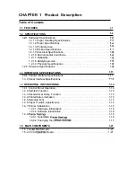
Page 95: ...Maintenance LX 300 Service Manual k w n M IL f Figure 6 1 LX 300 Lubrication Points 6 2 Rev A ...

Page 96: ... A 8 C130 MAIN Board Assembly Component Layout A 9 C130 PSB PSE Board Assembly Component Layout A 9 LX 300 Exploded Diagram l A 10 LX 300 Exploded Diagram 2 A n LX 300CaseOutline Drawing A 14 List of Tables Table A 1 Connector Summary A 2 Table A 2 Connector Pin Assignments CN2 A 2 Table A 3 Connector Pin Assignments CN3 A 2 Table A 4 Connector Pin Assignments CN4 A 2 Table A 5 Connector Pin Assig...

Page 97: ... are comected functions and sizes of the connectors I printer Mechanism I I MOTOR ASSY PF I Release Lever Position Sensor EEcl HOST COMPUTER El Table A 1 sumrnarizes the IBOARD ASSY PSB I PSE EJ P CN1 BOARD ASSY MAIN I Figure A 1 Cable m CN1O CN11 CS BOARD I Color Upgrade Kit II Connections Rev A A 1 ...

Page 98: ...ts CN2 Pin I o Signal Name Function 1 0 CR A CR motor assembly Phase A 2 0 CR B CR motor assembly Phase B 3 CRCOM CR motor assembly Common 4 CRCOM CR motor assembly Common 5 0 CR A CR motor assembly Phase A 6 0 I CR B I CR motor assembly Phase B Table A 3 Connector Pin Assignments CN3 Pin I o Signal Name Function 1 0 PF A PF motor assembly Phase A 2 0 PF B PF motor assembly Phase B 3 PFCOM PF moto...

Page 99: ...on 1 I PE PE sensor 2 GND Signal ground Table A 7 Connector Pin Assignments CN7 Pin I o Signal Name Funotion 1 I HP HP sensor 2 GND Signal ground Table A 8 Connector Pin Assignments CN8 Pin I o Signal Name Function 1 I RELSW Release Lever Position Sensor 2 GND Signal Ground Table A 9 Connector Pin Assignments CN9 CN1O CN11 Pin I o Signal Name Function 1 35 35 VDC 2 CS HOLD 5 VDC 3 5V DC 5 VDC 4 0 ...

Page 100: ...Appendix LX41M Service Manual I 1 4 T P 1 u r 1 NU m l 0 0 I w 1 I Figure A 3 C130 PSB Board Assembly Circuit Diagram Rev A A 7 ...

Page 101: ...LX 3 M Sarvice Manual Appendix M 0 z m I t N 4 u l IL 0 1 a u 1 I M F a N In mm 1 3 a u la 1 I Figure A 4 C130 PSE Board Assembly Circuit Diagram A a Rev A ...

Page 102: ...X 3tM Service Mhnuai A 3 CIRCUIT BOARD COMPONENT LAYOUT Swl SU2 fli n 0 2 3 81 9 RH2 RL Figure A 5 C130 MAIN Board Assembly Component Layout J I 1 Figure A 6 C130 PSB PSE Board Assembly Component Layout Rev A A 9 ...

Page 103: ...LX 3 M Samica Manual Appandix A 4 EXPLODED DIAGRAM 0 l T Figure A 7 LMOO Exploded Diagram 1 A 10 Rev A i ...

Page 104: ...Appendix LX Service Manual Rev A A n ...

Page 105: ...PSE WIRE HARNESS POWER CABLE ASSY POWER CABLE ASSY POWER CABLE ASSY PRINTER MECHANISM M 3G1 O FRAME LE17 FRAME RIGHT MOTOR PF Ref No 504 505 506 507 508 509 510 511 512 513 514 515 516 517 518 519 520 521 522 523 524 525 526 527 528 529 531 532 537 541 542 549 550 Description DETECTOR LEAF B1 HARNESS TR LEVER DISENGAGE COMPRESSION SPRING 200 TRACTOR REDUCTION GEAR PAPER FEED REDUCTION GEAR C B B S...

Page 106: ... P B SCREW M3 X 8 COMPRESSION SPRING 800 COMPRESSION SPRING 500 DAMPER DAMPER BASE SHEET PE DETECTOR FRAME TR LEIT FRAME TR RIGHT ef No El 564 565 566 567 568 569 570 571 572 573 574 575 Description P ROM TCNOO TRACTOR LEIT TRACTOR RIGHT SHAH TR SHAIT GUIDE TR PAPER SUPPORT SPURGEAR 17 RETAINING RING TYPE E 5 RETAINING RING TYPE E 6 ROLLER SUB ASSY EJ ROLLER EJ TRANSMISSION ROLLER EJ SUPPORT HOLDE...

Page 107: ...LX WI Sewice Manual Appendix A 5 CASE OUTLINE DRAWING c1 II II r r A 132rnrn v L l J Figure A 9 LX 300 Case Outline Drawing A 1 4 Rev A ...

Reviews: