4. Log
File
IMU/USB Interface Board
SEIKO EPSON CORPORATION
13
Logger Software User’s Guide (Rev.20181129)
4. Log File
This chapter describes the LOG files created by the Software.
A LOG file is created for each IMU. For each IMU checked in the “Connect” in the Serial Port settings, the
Software outputs a LOG file. The IMU number is added to the end of the filename of each LOG file.
4.1
Raw Data LOG
This section describes items recorded when the raw data format is selected as the data format used for the LOG
file.
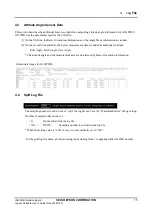
(1)
On the first line, the sampling start date and time (year, month, day, and time (unit: 1/100 second)) is
printed (Based on the PC OS clock) and Logger version.
(2)
On the second line, the IMU Product model number, Firmware version, Serial number.
(3) On the third line, the IMU Port number, sampling interval, Filter Type, number of TAPs are printed.
(4) On the fourth line, the scale factor of angular velocity and acceleration are printed.
(5) On the fifth line, the comment is printed.
(6) On the sixth line, the measurement data column heading are printed.
(7) On the seventh line and after, the measurement data are printed. The following items are recorded as
the measurement data.
•
Sample No: Sample number
•
time: Elapsed time
(Note: The elapsed time represents the time generated in the built-in timer inside the IMU.)
•
Gx: Angular velocity (X-axis), Gy: Angular velocity (Y-axis), Gz: Angular velocity (Z-axis)
•
Ax: Acceleration (X-axis), Ay: Acceleration (Y-axis), Az: Acceleration (Z-axis)
•
Ts: Temperature
(Note: This is a reference value used for internal temperature compensation. We provide no guarantee that the value gives an
accurate representation of the internal temperature.)
•
GPIO: GPIO information
*only for V340PDD0.
•
Count: SamplingCount or ResetCount
•
CheckSum
:
Checksum value , CheckResult
:
OK or NG
Output data image for V340PDD0


