background image

SERVICE MANUAL

CONFIDENTIAL

Color Inkjet Printer

M200/M201, M205, M100/M101, M105

SEMF12-012

Summary of Contents for M200

Page 1: ...SERVICE MANUAL CONFIDENTIAL Color Inkjet Printer M200 M201 M205 M100 M101 M105 SEMF12 012 ...

Page 2: ...EIKO EPSON would greatly appreciate being informed of them The contents of this manual are subject to change without notice The above not withstanding SEIKO EPSON CORPORATION can assume no responsibility for any errors in this manual or the consequences thereof EPSON is a registered trademark of SEIKO EPSON CORPORATION Note Other product names used herein are for identification purpose only and ma...

Page 3: ... to personal injury or damage of the product 1 Repairs on Epson product should be performed only by an Epson certified repair technician 2 No work should be performed on this product by persons unfamiliar with basic safety knowledge required for electrician 3 The power rating of this product is indicated on the serial number rating plate Never connect this product to the power source whose voltage...

Page 4: ...oller Gears Rollers LCD Scanner Sensor Exterior parts 14 Never use oil or grease other than those specified in this manual Use of different types of oil or grease may damage the component or give bad influence on the printer function 15 Apply the specified amount of grease described in this manual 16 Make the specified adjustments when you disassemble the printer 17 When cleaning this product foll...

Page 5: ...ols are used throughout this manual either to provide additional information on a specific topic or to warn of possible danger present during a procedure or an action Pay attention to all symbols when they are used and always read explanation thoroughly and follow the instructions Indicates an operating or maintenance procedure practice or condition that if not strictly observed could result in se...

Page 6: ...Confidential Revision Status Revision Date of Issue Description A October 17 2012 First Release ...

Page 7: ...uring Operation 27 2 2 Disassembly Reassembly Procedures 31 2 2 1 Configuration 31 2 2 2 Disassembly Flowchart 32 2 2 2 1 Multifunction Printer specific parts 34 2 2 2 2 Singlefunction Printer specific parts 37 2 2 2 3 Common Printer Mechanism 40 2 2 2 4 Unit Assy 42 2 2 3 Disassembly Flowchart Printhead Main Board 45 2 3 Detailed Disassembly Reassembly Procedure for each Part Unit 46 2 4 Routing ...

Page 8: ...on A Confidential Chapter 5 Appendix 5 1 Connector Diagram 81 5 2 Points to be checked before packing the printer 82 5 3 Protection for Transportation 83 5 3 1 Securing the CR Unit 83 5 3 2 Securing the Paper Support Paper Support Sub 84 ...

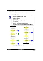
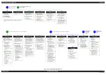
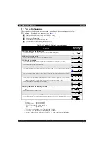
Page 9: ...Confidential CHAPTER 1 TROUBLESHOOTING ...

Page 10: ...Scanner unit therefore the troubleshooting related to the ADF Scanner unit is not applied If the reason for the return is evident first check the phenomenon user claims recurs then proceed to the troubleshooting ADF Scanner failure Printer failure only 1 If the Hopper of ASF on the returned product touches the LD Roller the initial ink charge has not been completed for the product yet 2 In case of...

Page 11: ...to print on the other side No Power Presumable Cause PS Unit damage Main Board damage Major Troubleshooting PS Unit replacement Main Board replacement Poor Printing Phenomenon Poor printing quality Ink stain on paper Dot missing Paper eject without printing Presumable Cause Driver Panel mis setting Contamination of CR scale Contamination of Printhead cover Printhead damage Ink clogging of Printhea...

Page 12: ...on 1 1 Initializes the Printhead and checks for the fuse on the circuit boards in the printer 3 2 Checking for waste ink overflow 2 1 Checks the waste ink counter if the waste ink overflow is occurring 3 Seeking the home position 3 1 The CR Unit moves to the 80 digit side slowly and confirms it touches the Change Lever CR lock 3 2 The CR Unit moves to the 0 digit side slowly 3 3 After the PE Senso...

Page 13: ... position and displays on the LCD or with flashing LEDs that the paper jam error occurs When the user removes the paper and releases the paper jam error by panel operation the normal power on sequence from No 1 Table 1 1 is executed again 2 To recover from the maintenance error the dedicated software that can be downloaded from the web site which can be accessed from STM3 is required The printer o...

Page 14: ...eration The following describes the panel operation for the product to display the fatal error code Method of displaying the fatal error code 1 Press the following buttons simultaneously while the fatal error is occurring Menu button Stop button OK button Figure 1 2 Displaying the Fatal Error Code 1 2 Check the displayed fatal error code Figure 1 3 Displaying the Fatal Error Code 2 Only the printe...

Page 15: ...ted detached scale Encoder Sensor failure CR Motor failure CR Unit drive mechanism overload paper jam foreign object insufficient grease deformation of the Main Frame Some part may be detached Paper Guide Upper Assy Cap Assy Cable disconnection Main Board failure Motor driver failure 08H CR load position reverse error CR Encoder failure contaminated detached scale Encoder Sensor failure Main Board...

Page 16: ...oad error PF Motor failure PF drive mechanism overload paper jam foreign object Tooth skip of the PF Timing Belt Improper tension of the PF Timing Belt Cable disconnection Motor drive time error D1H CR PID driving time error Main Board failure Firmware failure D2H CR load position driving time error Change Lever failure CR Motor failure Main Board failure Motor driver failure D3H PF PID driving ti...

Page 17: ...rror name Possible cause 10H Home position detection error CIS Module failure Scanner Housing Upper failure home seek pattern 1 is dirty Scanner Housing Lower failure the rack section 2 is damaged Scanner Motor failure Insufficient grease Foreign object FFC disconnection failure Main Board failure 14H Measurement error Scanner Motor failure Insufficient grease Foreign object Gear failure Deformati...

Page 18: ...Confidential CHAPTER 2 DISASSEMBLY REASSEMBLY ...

Page 19: ...code 2 1 2 Jigs Note If performing the disassembling reassembling procedure is difficult using tweezers such as when reassembling Cap Lever Cap Assy p52 the spring hook jig helps you to remove attach the spring easier 2 1 2 1 Making the Spring Hook Jig Fold a clip commercial item as shown in Fig 2 1 Figure 2 1 Making the Spring Hook Jig In this chapter the product names are called as follows M200 ...

Page 20: ...2 ADF Paper Guide Cover Assy p35 Paper Support Cover p35 Bevel Gear Shaft p42 Combination Gear 24 9 6 p42 ADF Document Support p42 ADF Pad Assy p42 Scanner Unit p42 Scanner Housing Upper p42 Scanner Carriage Unit p42 Scanner Housing Lower p42 CIS Module Unit p42 Scanner Motor p42 2 Tray Front Assy p34 3 Frame Base Assy p41 4 Panel Unit p37 Panel Board p43 Panel Button p43 Panel Housing Upper Assy ...

Page 21: ...er p34 4 Printhead p34 14 Ink Supply Tank Assy p35 Cap p35 Valve Lever p43 Ink Supply Tank Tube Assy p43 Housing Ink Supply Tank p43 Ink Supply Tank p43 5 CR Encoder Sensor p44 6 Adapter p35 7 CR Unit p44 15 Ink Supply Tube Guide 1st p35 8 PF Roller Unit p44 16 Joint p35 9 Star Wheel Holder Assy p36 17 Ink Supply Tube Guide 2nd p35 10 Paper Guide Front Unit p34 18 Ink Supply Tube p35 No Name No Na...

Page 22: ...ingbelt p40 2 EJ Roller p36 6 PF Scale p40 3 Ethernet Board Assy p36 M200 M100 Series 7 PF Encoder Sensor p40 4 PF Motor Assy p44 8 EJ Roller Gear p40 No Name No Name 1 CR Motor p40 7 Waste Ink Pad Assy p34 2 Pump Unit p44 8 Paper Back Lever p34 3 LD Roller Assy p40 9 Retard Roller Assy p34 4 LD Roller Cover p41 10 PE Sensor Lever p40 5 Head FFC p44 11 PS Unit p40 6 Main Board p40 1 2 8 4 6 7 3 5 ...

Page 23: ...0 23 0 23 Tray Front Assy 0 22 1 35 1 57 Tray Front 0 15 0 15 Tray Front Support 0 22 0 22 Paper Guide Front Unit 0 49 8 13 9 02 Waste Ink Pad Assy 0 42 0 45 1 27 Paper Back Lever 1 52 1 52 Retard Roller Assy 2 00 0 47 2 47 FFC Cover Outer 0 26 0 26 Holder Board 0 56 0 56 Printhead 2 20 18 47 21 07 ADF Paper Guide Cover Assy 0 25 0 25 ADF Cable Cover 0 27 0 27 Paper Support Cover 0 06 0 06 Documen...

Page 24: ...er 5 05 5 05 CIS Module Unit 5 28 5 28 Spacer 5 44 5 44 CIS Module 5 44 5 44 Scanner Motor Gear Cover 5 58 5 58 Combination Gear 18 4 9 66 6 05 6 05 Scanner Carriage Unit 6 09 6 09 Scanner Motor 8 25 8 25 CIS Holder Unit 8 25 8 25 Scanner Housing Lower 6 09 6 09 Housing Left 4 19 4 19 Ethernet Cover 4 25 4 25 Panel FFC Cover 3 04 3 04 Hinge 3 02 3 02 Housing Right 5 32 5 32 Strengthen Plate Upper ...

Page 25: ...oller Shaft Assy 7 50 7 50 Shield Plate 7 43 7 43 Main Board EEPROM Data Copy OK 8 39 1 10 9 49 EEPROM Data Copy NG 8 39 28 27 37 06 CR Motor 9 08 1 00 10 08 PE Sensor Lever 10 05 0 47 10 52 CR Scale 9 16 3 07 12 23 CR Driven Pulley Assy 9 48 9 48 CR Scale Cover Frame 8 35 8 35 LD Roller Cover 8 59 8 59 FFC Holder 9 06 9 06 Main Frame Assy 16 06 12 45 28 51 Antistatic Cloth 14 40 14 40 Paper Guide...

Page 26: ... through this film to keep ink supply to the Printhead stable If the film gets wet with ink the ink in the tanks is not properly vented and printing may not be capable In order to prevent this from occurring make sure to place the Ink Supply Tank Assy as shown below after removing it Figure 2 7 How to Place the Ink Tank Assy Ink Supply Tank Assy Ink Supply Tank Assy Ink Supply Tank Assy Do not pla...

Page 27: ... disassembly reassembly flowchart See 2 2 Disassembly Reassembly Procedures p31 Figure 2 8 Location Parts When ink may spill Location Joint Removing the Ink Supply Tank Tube Assy Ink Supply Tube from the Joint A Ink Supply Tank Removing the tubes of the Ink Supply Tank Tube Assy from the Joint Removing the tubes of the Ink Supply Tank Tube Assy from the Ink Supply Tank A B Ink Supply Tank Tube Ass...

Page 28: ...10 Adapter Even observing the points described in this section ink may spill in the following situations Therefore be careful not to contaminate the inside of the printer or its surroundings by preparing the container to receive the leaked ink or the like When removing the Ink Supply Tank Tube Assy w Valve Assy some ink will spill from both ends of the tube even the Valve Lever is closed When remo...

Page 29: ...dure 1 Remove the Housing Rear ADF Scanner Unit Housing Left Hinge Housing Right 2 With the choke value closed p 28 place the Ink Supply Tank Assy on a place where its bottom is higher than the top of the Printhead 3 Prepare a container for ink to discharge then disconnect the Ink Supply Tank Tube from the joint and put its tip into the container for the ink 4 Open the choke valve to discharge the...

Page 30: ...ect the tube from the injector then connect the Ink Supply Tube to the joint Figure 2 12 Discharging Ink 2 It is recommended that the ink in the Ink Supply Tank should be discharged completely before proceeding to disassembling reassembling After all the reassembling work is complete the discharged ink of each color should be refilled back to the Ink Supply Tank before performing the adjustment Co...

Page 31: ...nter specific parts Common Printer Mechanism and the Unit Assy Each section describes the following contents Figure 2 13 Configuration No Item Description Compatible Model 2 2 2 1 Multifunction Printer specific parts Describes the disassembly flowchart for the Multifunction Printer specific parts M200 Series M205 Series 2 2 2 2 Singlefunction Printer specific parts Describes the disassembly flowch...

Page 32: ...nction Printer Singlefunction Printer M200 Series M205 Series M100 Series M105 Series ADF Scanner O O Panel 2Line Bitmap type O O LED Button type O O Wireless LAN O O Wired LAN O O Disassembly Flowchart Start Position p 34 p 34 p 37 p 37 Table 2 3 Components According to Functions Item Specification ADF Scanner The following part is not mounted on the models without the ADF Scanner ADF Scanner Uni...

Page 33: ...items in the disassembling assembling procedure Indicates the reference page in blue letter Indicates supplementary explanation for disassembly is given Indicates the reference page in blue letter Indicates particular tasks to keep quality of the units are required Indicates the reference page in blue letter Indicates particular routing of cables is required Indicates the reference page in blue le...

Page 34: ... ZN 3C 2 0 5 kgf cm C B P TITE SCREW 2x8 F ZN 3C 2 5 kgf cm C B P TITE SCREW 2x8 F ZN 3C 4 1 kgf cm C B P TITE SCREW 3x10 F ZB 3C 6 1 kgf cm C B P TITE SCREW 3x10 F ZN 3C 6 1 kgf cm C B P TITE SCREW 3x10 F ZN 3C 5 1 kgf cm C B P TITE SCREW 2 5x8 F ZN 3C 2 5 0 5 kgf cm C B P TITE SCREW 3x10 F ZN 3C 7 1 kgf cm C B P TITE SCREW 3x8 F ZN 3C 6 1 kgf cm C B P TITE SCREW 3x6 F ZN 3C 6 1 kgf cm C B S TITE...

Page 35: ...ype torque list Symbol Screw Type Torque C B P TITE S P1 SCREW 3x12 F ZN 3C 6 1 kgf cm C B P TITE SCREW 2 6x5 F ZN 3C 6 1 kgf cm C B P TITE SCREW 2x8 F ZN 3C 2 0 5 kgf cm C B P TITE SCREW 2x8 F ZN 3C 2 5 kgf cm C B P TITE SCREW 2x8 F ZN 3C 4 1 kgf cm C B P TITE SCREW 3x10 F ZB 3C 6 1 kgf cm C B P TITE SCREW 3x10 F ZN 3C 6 1 kgf cm C B P TITE SCREW 3x10 F ZN 3C 5 1 kgf cm C B P TITE SCREW 2 5x8 F Z...

Page 36: ...e x1 S17 Model specific parts unit Common parts unit Screw type torque list Symbol Screw Type Torque C B P TITE S P1 SCREW 3x12 F ZN 3C 6 1 kgf cm C B P TITE SCREW 2 6x5 F ZN 3C 6 1 kgf cm C B P TITE SCREW 2x8 F ZN 3C 2 0 5 kgf cm C B P TITE SCREW 2x8 F ZN 3C 2 5 kgf cm C B P TITE SCREW 2x8 F ZN 3C 4 1 kgf cm C B P TITE SCREW 3x10 F ZB 3C 6 1 kgf cm C B P TITE SCREW 3x10 F ZN 3C 6 1 kgf cm C B P T...

Page 37: ...nk Supply Tube Guide 1st p37 Frame Base Sup port p38 Adapter Cover p38 Adapter p38 Extension spring x2 Ink Supply Tube Guide 1st 1 3 p 52 S7 Ink Tube Cover Paper Guide Front Unit 2 p 59 S7 F p 38 G p 38 Ink Supply Tank Cover p 54 Model specific parts unit Common parts unit Screw type torque list Symbol Screw Type Torque C B P TITE S P1 SCREW 3x12 F ZN 3C 6 1 kgf cm C B P TITE SCREW 2 6x5 F ZN 3C 6...

Page 38: ...ZN 3C 6 1 kgf cm C B P TITE SCREW 2 6x5 F ZN 3C 6 1 kgf cm C B P TITE SCREW 2x8 F ZN 3C 2 0 5 kgf cm C B P TITE SCREW 2x8 F ZN 3C 2 5 kgf cm C B P TITE SCREW 2x8 F ZN 3C 4 1 kgf cm C B P TITE SCREW 3x10 F ZB 3C 6 1 kgf cm C B P TITE SCREW 3x10 F ZN 3C 6 1 kgf cm C B P TITE SCREW 3x10 F ZN 3C 5 1 kgf cm C B P TITE SCREW 2 5x8 F ZN 3C 2 5 0 5 kgf cm C B P TITE SCREW 3x10 F ZN 3C 7 1 kgf cm C B P TIT...

Page 39: ...2x8 F ZN 3C 2 0 5 kgf cm C B P TITE SCREW 2x8 F ZN 3C 2 5 kgf cm C B P TITE SCREW 2x8 F ZN 3C 4 1 kgf cm C B P TITE SCREW 3x10 F ZB 3C 6 1 kgf cm C B P TITE SCREW 3x10 F ZN 3C 6 1 kgf cm C B P TITE SCREW 3x10 F ZN 3C 5 1 kgf cm C B P TITE SCREW 2 5x8 F ZN 3C 2 5 0 5 kgf cm C B P TITE SCREW 3x10 F ZN 3C 7 1 kgf cm C B P TITE SCREW 3x8 F ZN 3C 6 1 kgf cm C B P TITE SCREW 3x6 F ZN 3C 6 1 kgf cm C B S...

Page 40: ...om the Main Frame Assy remove the following parts before removing the Main Frame Assy FFC Cover Outer Holder Board Printhead p 34 Multifunction Printer p 37 Singlefunction Printer i ii p 34 Multifunction Printer p 37 Singlefunction Printer Main Board FFC Holder p36 Ethernet Board Assy p36 Model specific parts unit Common parts unit Screw type torque list Symbol Screw Type Torque C B P TITE S P1 SC...

Page 41: ... 59 p 73 Model specific parts unit Common parts unit Screw type torque list Symbol Screw Type Torque C B P TITE S P1 SCREW 3x12 F ZN 3C 6 1 kgf cm C B P TITE SCREW 2 6x5 F ZN 3C 6 1 kgf cm C B P TITE SCREW 2x8 F ZN 3C 2 0 5 kgf cm C B P TITE SCREW 2x8 F ZN 3C 2 5 kgf cm C B P TITE SCREW 2x8 F ZN 3C 4 1 kgf cm C B P TITE SCREW 3x10 F ZB 3C 6 1 kgf cm C B P TITE SCREW 3x10 F ZN 3C 6 1 kgf cm C B P T...

Page 42: ... p 56 p 73 CIS Holder Unit p 56 Scanner Motor 2 p 56 p 59 S8 ADF Paper Guide Cover Assy p35 ADF Paper Guide Cover Assy p35 ADF Cable Cover p35 Model specific parts unit Common parts unit Screw type torque list Symbol Screw Type Torque C B P TITE S P1 SCREW 3x12 F ZN 3C 6 1 kgf cm C B P TITE SCREW 2 6x5 F ZN 3C 6 1 kgf cm C B P TITE SCREW 2x8 F ZN 3C 2 0 5 kgf cm C B P TITE SCREW 2x8 F ZN 3C 2 5 kg...

Page 43: ...B P TITE SCREW 2 6x5 F ZN 3C 6 1 kgf cm C B P TITE SCREW 2x8 F ZN 3C 2 0 5 kgf cm C B P TITE SCREW 2x8 F ZN 3C 2 5 kgf cm C B P TITE SCREW 2x8 F ZN 3C 4 1 kgf cm C B P TITE SCREW 3x10 F ZB 3C 6 1 kgf cm C B P TITE SCREW 3x10 F ZN 3C 6 1 kgf cm C B P TITE SCREW 3x10 F ZN 3C 5 1 kgf cm C B P TITE SCREW 2 5x8 F ZN 3C 2 5 0 5 kgf cm C B P TITE SCREW 3x10 F ZN 3C 7 1 kgf cm C B P TITE SCREW 3x8 F ZN 3C...

Page 44: ...del specific parts unit Common parts unit Screw type torque list Symbol Screw Type Torque C B P TITE S P1 SCREW 3x12 F ZN 3C 6 1 kgf cm C B P TITE SCREW 2 6x5 F ZN 3C 6 1 kgf cm C B P TITE SCREW 2x8 F ZN 3C 2 0 5 kgf cm C B P TITE SCREW 2x8 F ZN 3C 2 5 kgf cm C B P TITE SCREW 2x8 F ZN 3C 4 1 kgf cm C B P TITE SCREW 3x10 F ZB 3C 6 1 kgf cm C B P TITE SCREW 3x10 F ZN 3C 6 1 kgf cm C B P TITE SCREW 3...

Page 45: ...ousing Upper Assy 5 13 p 47 S6 S21 FFC Cable 12 Housing Left Assy 5 6 p 47 S6 S16 Adapter Cover 1 4 p 49 S9 Adapter 1 p 54 Head FFC Ink Supply Tube Guide 1st 1 3 p 52 S7 Ink Supply Tank Cover p 54 Ink Tube Cover Frame Base Support Hopper 2 p 59 p 73 FFC Cable 10 Main Board FFC Holder 1 2 S15 FFC Cable 11 Shield Plate 3 p 52 S14 S17 Main Board 1 p 52 p 57 p 59 S15 Ethernet Board Assy 1 2 p 50 S7 Mo...

Page 46: ...25 8 20 4 M200 M205 Series Install the Spur Gear 25 8 20 4 as shown in the figure A above When installing the ADF Front Frame check that the Spur Gear 25 8 20 4 is installed on the position shown in the figure B above ADF Front Frame Diagram A Spur Gear 25 8 Spur Gear 20 4 Diagram B Spur Gear 20 4 Spur Gear 25 8 ADF Pad Assy M200 M205 Series Remove the ADF Pad Assy by removing the hooks x2 and dow...

Page 47: ...ay be interfered with the Hopper or the Scanner Unit Housing Right Housing Left Housing Upper Assy M100 M105 Series Remove the Housing Upper Assy by releasing the hooks x2 and ribs x3 shown in the figure above Tighten the screws in the order indicated in the figure above 3 4 2 Housing Upper Assy Hook Rib 1 C B P TITE SCREW 3x10 F ZN 3C 6 1 kgf cm Waste Ink Pad Assy When installing the Waste Ink Pa...

Page 48: ...using Left Housing Right Tighten the screws in the order indicated in the figure above Panel Unit Housing Right Housing Left 1 2 3 C B P TITE SCREW 3x10 F ZB 3C 6 1 kgf cm Panel Board Assy M200 M205 Series Tighten the screws in the order indicated in the figure above Tighten the grounding wire together on the position indicated in the figure above Tighten the grounding wire with screws on the dire...

Page 49: ...e to the hole of the Main Frame CR Scale Cover Frame Cutout Rib Rib 0 digit side Inset rib 80 digit side Align cutout Inset rib Main Frame CR Scale Cover Frame 1 2 3 CR Driven Pulley Assy CR Timing Belt When installing the CR Driven Pulley Assy and CR Timing Belt follow the procedure below 1 Install the CR Driven Pulley Assy to the Main Frame 2 Attach the Compression Spring 20 91 in the order from...

Page 50: ... Timing Belt Do not hold the PF Driven Pulley Assy when securing it with the screw in order to prevent applying improper tension to the PF Timing Belt When installing the PF Driven Pulley Assy follow the procedure below 1 Align the rib of the PF Driven Pulley Assy with the hook of the PF Motor Frame and install the PF Driven Pulley Assy 2 Attach the Compression Spring 5 07 to the protrusion of the...

Page 51: ...ame Base Insert the outside the rib of Frame Base Spur gear Extension Spring 0 137 Clutch LD Roller shaft Install Spur gear Extension Spring 0 137 Clutch LD Roller shaft as shown in the figure above Extension Spring 0 137 Clutch Spur gear LD Roller Shaft LD Roller LD Roller Assy Install the LD Roller Assy with the following condition in order to avoid the Change Lever and Paper Back Lever Using a ...

Page 52: ...ver and Frame Base Cap Lever Extension Spring 1 329 Cap Assy Extension Spring 0 65 Hook of Cap Assy Hook of Frame Base Step 6 Shaft B Shaft A Shaft C Cap Assy Step 2 Make sure the marking 10 1 mm from the tube end on the tube cannot be seen when viewed from the side Cap Slider Cutout Hole B Cap Lever Frame Base Hole A Hole C Step 1 3 5 Hook of Frame Base Hook of Cap Lever Step 7 Pump Unit When ins...

Page 53: ...ach the Valve Assy to the Housing Ink Supply Tank 3 Secure the Ink Supply Tank and Valve Assy to the Housing Ink Supply Tank with the three screws Lever section Hole Ink Supply Tank Housing Ink Supply Tank Housing Ink Supply Tank C B P TITE SCREW 3x6 F ZN 3C 6 1 kgf cm Dowel Positioning hole Ink Supply Tank Valve Assy Ink Supply Tube Install the Ink Supply Tube as follows 1 Mark the position 72 1 ...

Page 54: ...ed line 0 5 mm or less Ink Supply Tube Ink Supply Tank Tube Joint 0 5 mm or less Joint Cutout Joint Ink Supply Tube Ink Supply Tank Tube Adapter Be careful not to damage or peel off the film of the Adapter Use a precision screwdriver when releasing the hook of the Adapter Install the Ink Supply Tube to the adapter with its red line facing the right side of the adapter Connection of Ink Supply Tube...

Page 55: ...eassembly Detailed Disassembly Reassembly Procedure for each Part Unit 55 Confidential Refilling Ink Label Attach the Refilling Ink Label on the position shown in the figure above Refilling Ink Label M200 M205 Series Refilling Ink Label M100 M105 Series ...

Page 56: ...s Scanner FFC Insert the hole of the Housing Left and connect the connector CN11 of the Main Board through the ferrite core Grounding wire Insert the hole of the Housing Left and connect the Ribs of Main Board Shield Plate Sub Route the Scanner FFC inserting the hole of the Housing Left Housing Left Ribs of Main Board Shield Plate Sub Ferrite core Scanner FFC M200 M205 Series Route the Scanner FFC...

Page 57: ...b Double sided tape Panel FFC Frame Base Main Frame Housing Upper Assy Panel FFC Hole Right side of Main Board Connect the following cables FFCs to the Main Board as shown in the figure above CR Motor cable CN12 CR Encoder FFC CN6 Head FFC CN102 Secure with the double sided tape on the position shown above Main Board CN12 CN102 Head FFC CR Encoder FFC CN61 CR Motor cable Double sided tape Left sid...

Page 58: ...e hole of the Frame Base first and then route it through the rib of the Frame Base Put the ferrite core into the position shown in the figure above Bottom of Frame Base PS Unit cable Ferrite core PS Unit cable Frame Base Hole Rib PF Motor Route the PF Motor cable as follows 1 Pull out the PF Motor cable from the hole of the Frame Base 2 Install the PF Motor and secure the PF Motor cable black with...

Page 59: ...Confidential CHAPTER 3 ADJUSTMENT ...

Page 60: ...arry out the adjustment again When replacing the Main Board the adjustment should be made after performing the initial setting In this chapter the product names are called as follows M200 Series M200 M201 M205 Series M205 M100 Series M100 M101 M105 Series M105 The table items and marks used in the Required Adjustment List provided on the following pages have the following meanings O indicates that...

Page 61: ...Paper Guide Lower Porous Pad Remove Replace Printhead Remove 1 Replace O Waste Ink Pad Assy Remove Replace Retard Roller Assy Remove Replace Scanner Unit Remove Replace Scanner Motor Remove Replace PS Unit Remove Replace PF Driven Pulley Assy Remove O Replace O PF Timing Belt Remove O Replace O EJ Roller Remove Replace Hopper Remove Replace Printout pattern How to judge See 3 3 1 Checking the Plat...

Page 62: ...ce O Frame Base Replace O Table 3 1 Required Adjustment List Adjustment Type Mechanism adjustment Priority 1 2 3 Adjustment Item Checking the Platen Gap CR Belt tension check PF Belt tension check Purpose Check if the PG is within the standard Check the tension of the CR Timing Belt Check the tension of the PF Timing Belt Printout pattern How to judge See 3 3 1 Checking the Platen Gap p69 for the ...

Page 63: ...o the replaced parts To measure and correct the electrical variation of the motor and the power supply board To measure and correct the electrical variation of the motor and the power supply board To measure and correct the electrical variation of the motor Part Name Tray Front Assy Remove Replace O Star Wheel Holder Assy Remove Replace O O Paper Guide Front Unit Remove Replace O O O O Printhead R...

Page 64: ... to achieve higher print quality in band printing To align print start position at 0 digit side with that at 80 digit side in bidirectional band printing timing of firing ink droplet is adjusted through software control To reset the counter according to the replaced parts To measure and correct the electrical variation of the motor and the power supply board To measure and correct the electrical v...

Page 65: ...ns in paper feed accuracy to achieve higher print quality in band printing To align print start position at 0 digit side with that at 80 digit side in bidirectional band printing timing of firing ink droplet is adjusted through software control To reset the counter according to the replaced parts To measure and correct the electrical variation of the motor and the power supply board To measure and...

Page 66: ...ve higher print quality in band printing To align print start position at 0 digit side with that at 80 digit side in bidirectional band printing timing of firing ink droplet is adjusted through software control To reset the counter according to the replaced parts To measure and correct the electrical variation of the motor and the power supply board To measure and correct the electrical variation ...

Page 67: ... Board and Power Supply Board to determine the correction value used for estimating the current values of the motors Risks if the adjustment is not correctly made The printer cannot measure the current value of motor correctly then the heat generation caused by motor drive cannot be estimated accurately either and which may results in trouble such as incorrect control of motors when allotting a co...

Page 68: ...ge can operate without any problem is applied the printer cannot control the drive of the motors correctly which may result in occurrence or generation of scanner fatal error vibration or noises Procedure 1 Select from the menu of the Adjustment Program and press the Perform button to measure the correction value 2 Turn off the printer and turn it back on After the Scanner Carriage is operated the...

Page 69: ... specified jigs according to this manual If the PG cannot fall within the standard range after performing the platen gap check described in this section first check if the unit is correctly reassembled following the instructions in this manual Even if the unit is correctly reassembled but the PG still cannot fall within the standard range replace the unit with a new refurbished one The standard ra...

Page 70: ...the CR Unit to both ends and confirm the CR Unit touches the thickness gauges 2 8 Move the CR Unit to the center and place the thickness gauges 2 0 mm on the position B shown in Figure 3 1 9 Pull the CR Timing Belt to move the CR Unit to both ends and confirm the CR Unit touches the thickness gauges 2 Note 1 If the CR Unit comes in contact with the thickness gauges the PG is smaller than the stand...

Page 71: ...n check is complete Out of the standard range replace the unit with a new refurbished one Figure 3 2 Checking the CR Timing Belt Tension This printer is designed so that the each tension of the CR Timing Belt and PF Timing Belt fall within the expected range if you correctly reassemble the unit according to this manual However deformation of any related part s can cause improper tension of the bel...

Page 72: ...ension of the belt three times 4 Check the average of the measured values falls within the standard range Within the standard range the PF Timing Belt tension check is complete Out of the standard range reinstall the PF Driven Pulley Assy PF Timing Belt p50 and then perform the PF Timing Belt Tension Check again Figure 3 3 Checking the PF Timing Belt Tension Perform the PF Belt tension check befor...

Page 73: ...Confidential CHAPTER 4 MAINTENANCE ...

Page 74: ... are determined based on the results of the internal evaluations Therefore refer to 4 2 Lubrication Points and Instructions p75 for the repairing procedures below and apply the specified type and amount of the grease to the specified part of the printer mechanism 4 2 Lubrication Points and Instructions p75 also provides information about whether or not the parts which require lubrication are suppl...

Page 75: ...inter Type G 71 Application Amount 0 02 g Remarks Apply with injector then spread it all over the entire internal circumference of the bearing Scanner Unit Application Point Spread it all over internal circumference Part supply as ASP Yes Lubrication status when supplied as ASP Not lubricated Lubrication Point Shaft on the Bevel Gear Shaft 10 4 Type G 71 Application Amount Appropriate amount Remar...

Page 76: ...t supply as ASP Supplied as the Scanner Unit Lubrication status when supplied as ASP Lubricated Lubrication Point Guide rail of the Scanner Housing Lower x6 Type G 45 Application Amount 0 03 g x 6 points Remarks Do not apply directly on the head of the Guide rail Apply with injector Be careful not to let grease flow over Keep the grease spreading procedures Origin position side Drive Gear side Gui...

Page 77: ...n Point 1 Application Point Figure 4 10 Lubrication of the Frame Base 3 Part supply as ASP Supplied as Printer Mechanism Lubrication status when supplied as ASP Lubricated Lubrication Point Contact point x3 on the EJ Roller with the Frame Base Type G 71 Application Amount Appropriate amount Remarks Apply with injector Apply grease along the groove on the Frame Base Apply grease on the groove Apply...

Page 78: ...G 71 Application Amount Appropriate amount Remarks Apply with injector Check the lubrication condition and apply grease if necessary CR Driven Pulley Holder 2 Application Point 1 Application Point Figure 4 15 Lubrication of the LD Roller Assy Part supply as ASP Supplied as the LD Roller Shaft Lubrication status when supplied as ASP Not lubricated Lubrication Point Cam of the contact point with the...

Page 79: ...of the Paper Back Lever Part supply as ASP Yes Lubrication status when supplied as ASP Not lubricated Lubrication Point Contact points x2 on the Paper Back Lever with the Frame Base Type G 71 Application Amount 0 06 g x 2 points Remarks Apply with injector Lubricate before attaching the part Paper Back Lever Application Point ...

Page 80: ...Confidential CHAPTER 5 APPENDIX ...

Page 81: ...am In this chapter the product names are called as follows M200 Series M200 M201 M205 Series M205 M100 Series M100 M101 M105 Series M105 CN501 CN14 CN2 CN7 CN13 CN12 CN61 CN11 CN102 Printhead CIS PE Sensor CR Motor SCN Motor PF Motor USB CN3 CN2 CN4 PF Encoder CR Encoder WiFi Board AC in PS Board Main Board ADF Scanner Unit CN1 CN1 LCD Panel Board CN1 Panel Board CN1 CR Unit Panel Unit M200 M205 S...

Page 82: ...M105 Series Revision A 5 2 Points to be checked before packing the printer The Valve Lever is on the position shown below the Choke Valve is closed See Figure 2 10 All the caps of the Ink Supply Tank Assy are securely closed The opened ink bottle is not included in the box Valve Lever Cap ...

Page 83: ... CR Timing Belt and move the CR Unit to the 80 digit side slightly so that the CR Unit can touch the side of the tip on the Change Lever 3 Attach the not folded end of strong tape on the bottom of the CR Unit 4 Attach the strong tape on to the Housing Right and secure the CR Unit Figure 5 2 Securing the CR Unit In order to prevent damaging the Change Lever the CR Unit should be secured at the posi...

Page 84: ...two pieces of strong tape Multifunction Printer 1 Length 60 mm width 22 mm fold one end 5 2 mm 2 Length 50 mm width 22 mm fold one end 5 2 mm Singlefunction Printer 3 tapes Length 80 mm width 16 mm fold one end 5 2 mm Method Multifunction Printer 1 Attach the strong tape 1 to the position on the following diagram A and secure the Paper Support Sub 2 Attach the strong tape 2 to the position on the ...

Page 85: ... Attach the strong tape 3 tapes to the position on the following diagram and secure the Paper Support Paper Support Sub on the Housing Upper Assy Figure 5 4 Securing the Paper Support Paper Support Sub Singlefunction Printer Rear Paper Support Paper Support Sub Folded ends Paper Support Paper Support Sub Strong tape ...

Reviews: