S5U1C63000H2 MANUAL
EPSON
11
(S1C63 FAMILY IN-CIRCUIT EMULATOR)
CHAPTER 5: OPERATION AND FUNCTION OF S5U1C63000H2
CHAPTER
5 O
PERATION
AND
F
UNCTION
OF
S5U1C63000H2
This chapter describes operations, functions in detail and restrictions in the emulation mode of the
S5U1C63000H2.
5.1 General of Operation
ICE control
processor
Emulation control portion
Trace control portion
Break control portion
Target monitor portion
Flash memory
Emulation program memory
Emulation data memory
RS-232C
host interface
ICE firmware
S1C63000
CPU
To peripheral circuit board
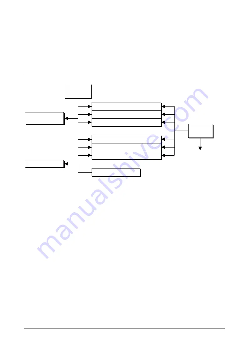
Fig. 5.1.1 Functional block diagram of S5U1C63000H2
Figure 5.1.1 shows the functional block diagram of the S5U1C63000H2.
The S5U1C63000H2 has a processor to control in-circuit emulation, which processes the ICE commands.
The function to execute or stop target programs by the S1C63000 CPU is called emulation, of which
control is done by the emulation control portion.
Operation that the S1C63000 CPU is working (specified by the G command) and single step operation
(specified by the S or N commands) are called emulation mode, on which the EMU LED goes on and
program counter display LEDs real timely indicate the program counter of the program running. The
other status is called standby mode, which turns the EMU LED off and makes the program counter
display LEDs show program counter position at the break.
The target program to be executed with the S1C63000 CPU is stored in the emulation program memory
and data RAM area of the S1C63000 CPU is assigned to the emulation data memory. Loading a program
from the flash memory or the host is done by the S5U1C63000H2 control processor in the standby mode.
The trace control portion records execution bus cycle of the S1C63000 CPU and consists of a memory of
8,192 words
×
120 bits. Such large size memory enables the register value inside the S1C63000 CPU to be
real timely recorded. The tracing is done in the emulation mode and it is analyzed by the S5U1C63000H2
control processor in the standby mode.
The break control portion compares the bus condition of the S1C63000 CPU with break points and stops
the execution of the target program upon coincident. The break can be also real timely made by register
values of the S1C63000 CPU. While a target program is running, the target monitor portion of the
S5U1C63000H2 control processor monitors executing program counter value of the S1C63000 CPU and
RAM contents at watching points. The monitored result is displayed as on-the-fly information. The
S1C63000 CPU can real timely execute the target program while the information is displayed.
Summary of Contents for MF1436-02
Page 4: ......


