Setup & Operation 6. Options
88
N6 Rev.2
Camera and N6 series Manipulator Joint #5 motion range (reference values)
A
B
C
D
X
USB camera,
GigE camera
−
75 deg.
~ +125 deg.
−
65 deg.
~ +125 deg.
−
55 deg.
~ +125 deg.
−
45 deg.
~ +125 deg.
95.5 mm
A
B
C
D
Y
33 mm
13 mm
-7 mm
-27 mm
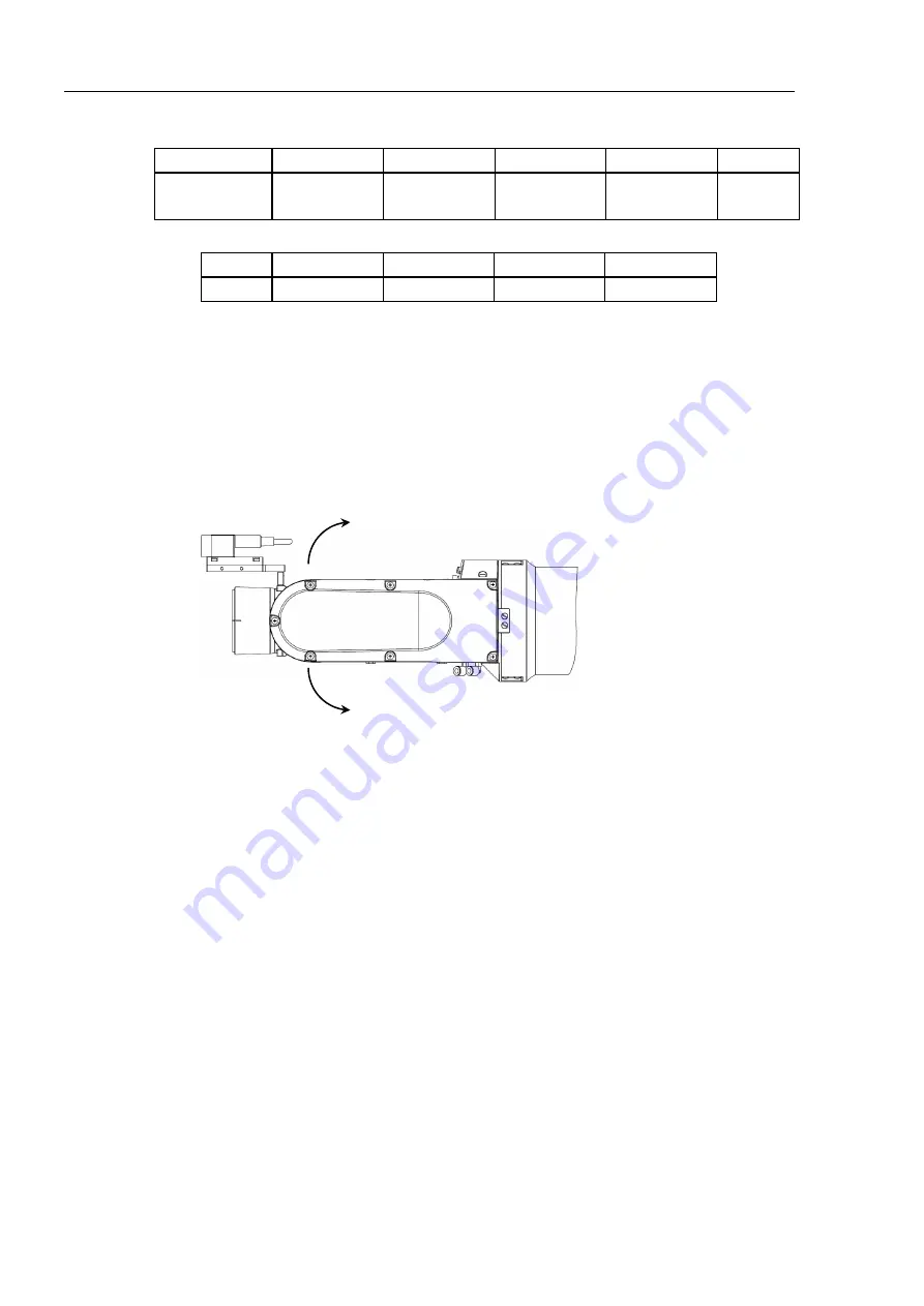
The Joint #5 motion range varies depending on the mounting position of camera mid plate
and the camera you are using.
The table below shows the motion range (reference values) based on the available cameras
for this option and the mounting positions of the camera mid plate. The values in the
table may vary depending on how to secure the cables.
Direction of the Joint #5 motion
+
-
Summary of Contents for N6 Series
Page 1: ...Rev 2 EM187R3735F 6 Axis Robots N6 series MANIPULATOR MANUAL ...
Page 2: ...Manipulator manual N6 series Rev 2 ...
Page 8: ...vi N6 Rev 2 ...
Page 14: ......
Page 27: ...Setup Operation 1 Safety N6 Rev 2 15 N6 A850 R C A D F G F E H G F B G F G F F F N6 A850 BR F ...
Page 34: ...Setup Operation 2 Specifications 22 N6 Rev 2 N6 A850 BR Cable direction Upward ...
Page 52: ...Setup Operation 3 Environment and Installation 40 N6 Rev 2 N6 A850 R Maximum motion range 802 ...
Page 66: ...Setup Operation 4 End Effectors 54 N6 Rev 2 N6 A850 R Unit mm ...
Page 104: ......
Page 274: ...Maintenance 4 Cable 262 N6 Rev 2 4 7 1 Signal Power cable ...
Page 275: ...Maintenance 4 Cable N6 Rev 2 263 ...
Page 276: ...Maintenance 4 Cable 264 N6 Rev 2 4 7 2 User Cable ...


