Maintenance 4. Cable
172
N6 Rev.2
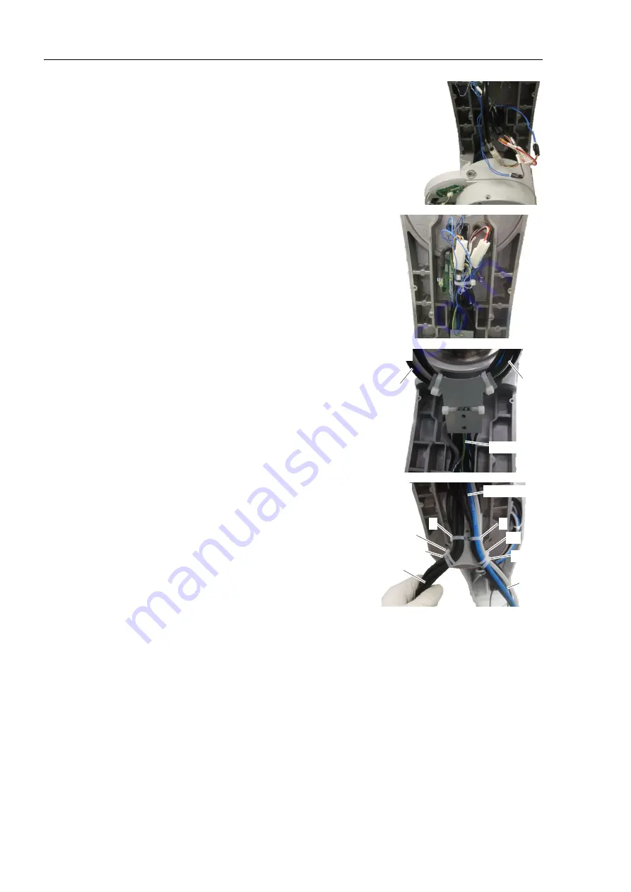
(25) Connect the connectors.
Connectors: PW2, BR2, PW3, BR3
(26) Bundle the cables.
Cable ties (AB200) × 1
(27) Fix the cable unit to the cable fixing plate.
Be careful for the following:
Cable ties (AB200) × 4 (1 to 4)
Tightening strength: 85
±
5 N
Front
A
B
Base side
Cable A
Set the A5 of the cable tie to the cable fixing
plate and fix it by using the cable ties 1 and
2. Make sure that the gray colored cable is
on the plate side.
Cable B
Set the B5 of the cable tie to the cable fixing
plate and fix it by using the cable ties 3 and
4. Make sure that the two air tubes (blue
and white) are on the opposite side of the
plate.
Back
Base side
B
A
1
3
B5
A5
2
4
Refer to the figure for positions of the cable tie heads.
Rotate the heads of the cable ties A5 and B5 to set positions.
Be careful for the orders and the positions of the cable ties.
Distance between the cable tie 1 and A5, and 3 and B5 should be as close as possible.
Improper order or position of the cable tie may shorten the life cycle of the cables.
NOTE
Summary of Contents for N6 Series
Page 1: ...Rev 2 EM187R3735F 6 Axis Robots N6 series MANIPULATOR MANUAL ...
Page 2: ...Manipulator manual N6 series Rev 2 ...
Page 8: ...vi N6 Rev 2 ...
Page 14: ......
Page 27: ...Setup Operation 1 Safety N6 Rev 2 15 N6 A850 R C A D F G F E H G F B G F G F F F N6 A850 BR F ...
Page 34: ...Setup Operation 2 Specifications 22 N6 Rev 2 N6 A850 BR Cable direction Upward ...
Page 52: ...Setup Operation 3 Environment and Installation 40 N6 Rev 2 N6 A850 R Maximum motion range 802 ...
Page 66: ...Setup Operation 4 End Effectors 54 N6 Rev 2 N6 A850 R Unit mm ...
Page 104: ......
Page 274: ...Maintenance 4 Cable 262 N6 Rev 2 4 7 1 Signal Power cable ...
Page 275: ...Maintenance 4 Cable N6 Rev 2 263 ...
Page 276: ...Maintenance 4 Cable 264 N6 Rev 2 4 7 2 User Cable ...


