Maintenance 4. Cable
242
N6 Rev.2
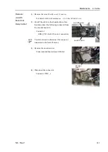
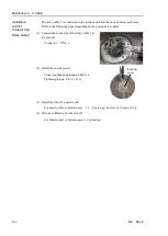
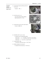
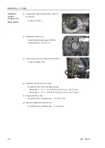
Removal
Joint #3
Actuator Unit
Relay Cable 1
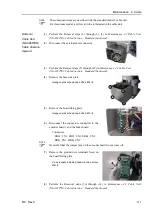
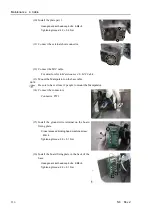
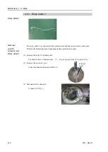
(1) Remove the Arm #2 cover.
For details, refer to the following sections:
Maintenance 3.7.1 N6-A1000** (Arm #2 Cover, Arm #1 Side)
Maintenance 3.7.2 N6- A850**R (Arm #2 Cover, Arm #1 Side)
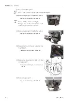
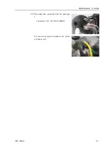
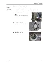
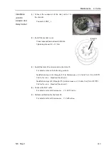
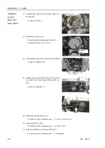
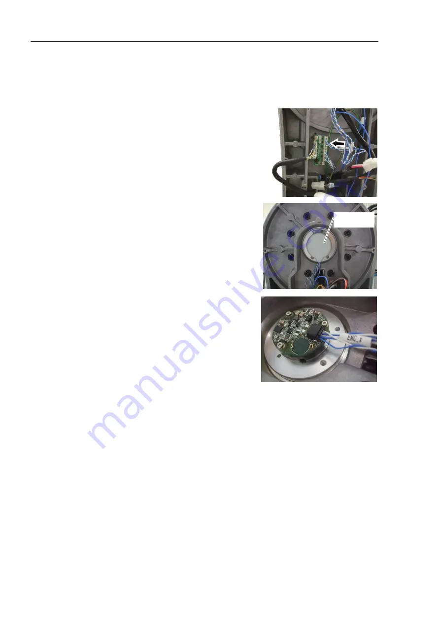
(2) Remove the connector from the encoder
board 2.
Connector: EB0x_CN2 (Joint #3 side)
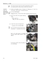
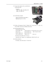
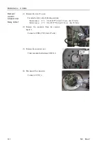
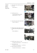
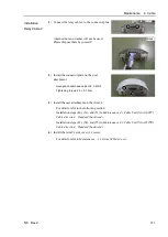
(3) Remove the encoder cover.
Cross recessed head screws: 3-M2.5
×
6
Encoder
cover
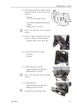
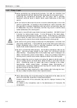
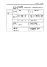
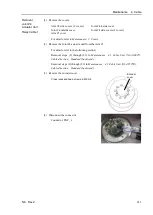
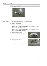
(4) Disconnect the connector.
Connector: ENC_x
Summary of Contents for N6 Series
Page 1: ...Rev 2 EM187R3735F 6 Axis Robots N6 series MANIPULATOR MANUAL ...
Page 2: ...Manipulator manual N6 series Rev 2 ...
Page 8: ...vi N6 Rev 2 ...
Page 14: ......
Page 27: ...Setup Operation 1 Safety N6 Rev 2 15 N6 A850 R C A D F G F E H G F B G F G F F F N6 A850 BR F ...
Page 34: ...Setup Operation 2 Specifications 22 N6 Rev 2 N6 A850 BR Cable direction Upward ...
Page 52: ...Setup Operation 3 Environment and Installation 40 N6 Rev 2 N6 A850 R Maximum motion range 802 ...
Page 66: ...Setup Operation 4 End Effectors 54 N6 Rev 2 N6 A850 R Unit mm ...
Page 104: ......
Page 274: ...Maintenance 4 Cable 262 N6 Rev 2 4 7 1 Signal Power cable ...
Page 275: ...Maintenance 4 Cable N6 Rev 2 263 ...
Page 276: ...Maintenance 4 Cable 264 N6 Rev 2 4 7 2 User Cable ...

