Maintenance 8. Calibration
360
N6 Rev.2
EPSON
RC+
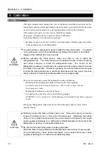
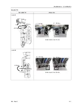
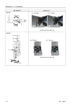
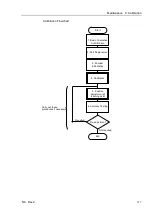
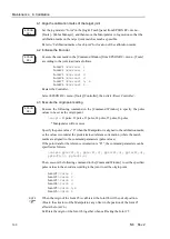
4-1. Align the calibration marks of the target joint
Set the jog mode to “Joint” in the [Jog & Teach] panel from EPSON RC+ menu -
[Tools] - [Robot Manager], and then move the Manipulator in Jog motion so that the
calibration marks on the target joint match as much as possible.
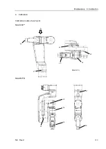
Refer to “Calibration marks of each joint” for location of the calibration marks.
4-2
Initialize the Encoder.
EPSON
RC+
Execute the command in the [Command Window] from EPSON RC+ menu - [Tools]
according to the joint to adjust as follows.
Joint #1
>Encreset 1
Joint #2
>Encreset 2
Joint #3
>Encreset 3
Joint #4
>Encreset 4
Joint #5
>Encreset 5, 6
Joint #6
>Encreset 6
Restart the Controller.
Select EPSON RC+ menu-[Tools]-[Controller], then click <Reset Controller>.
4-3 Execute the origin point setting
EPSON
RC+
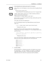
Execute the following command in the [Command Window] to specify the pulse
values to be set as the origin point.
>calpls
J1 pulse, J2 pulse, J3 pulse, J4 pulse, J5 pulse, J6 pulse
* Manipulator will not move.
Specify the pulse values “0” when the Manipulator is aligned to the calibration marks,
or the values recorded at the predetermined reference orientation (where the match
marks are aligned) to the command parameters (pulse values).
If the point data for the reference orientation is “P1”, the command parameters can be
specified as follows
>calpls ppls(P1,1), ppls(P1,2), ppls(P1,3), ppls(P1,4),
ppls(P1,5), ppls(P1,6)
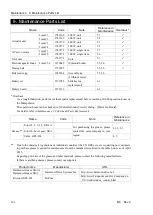
Then, execute the following command in the [Command Window] to set the specified
pulse values to the encoder according to the joint to set the origin point.
Joint #1
>Calib 1
Joint #2
>Calib 2
Joint #3
>Calib 3
Joint #4
>Calib 4
Joint #5
>Calib 5,6
Joint #6
>Calib 6
When the origin of the Joint #5 is calibrated, the Joint #6 will be out of position.
(Due to the structure of the Manipulator, any offset in the position of the Joint #5
affects the Joint #6.)
Calibrate the origin of the Joint #6 together when calibrating the Joint #5.
NOTE
Summary of Contents for N6 Series
Page 1: ...Rev 2 EM187R3735F 6 Axis Robots N6 series MANIPULATOR MANUAL ...
Page 2: ...Manipulator manual N6 series Rev 2 ...
Page 8: ...vi N6 Rev 2 ...
Page 14: ......
Page 27: ...Setup Operation 1 Safety N6 Rev 2 15 N6 A850 R C A D F G F E H G F B G F G F F F N6 A850 BR F ...
Page 34: ...Setup Operation 2 Specifications 22 N6 Rev 2 N6 A850 BR Cable direction Upward ...
Page 52: ...Setup Operation 3 Environment and Installation 40 N6 Rev 2 N6 A850 R Maximum motion range 802 ...
Page 66: ...Setup Operation 4 End Effectors 54 N6 Rev 2 N6 A850 R Unit mm ...
Page 104: ......
Page 274: ...Maintenance 4 Cable 262 N6 Rev 2 4 7 1 Signal Power cable ...
Page 275: ...Maintenance 4 Cable N6 Rev 2 263 ...
Page 276: ...Maintenance 4 Cable 264 N6 Rev 2 4 7 2 User Cable ...

