Setup & Operation 3. Environment and Installation
N6 Rev.2
35
3.3 Mounting Dimensions
3.3.1 Mounting Area
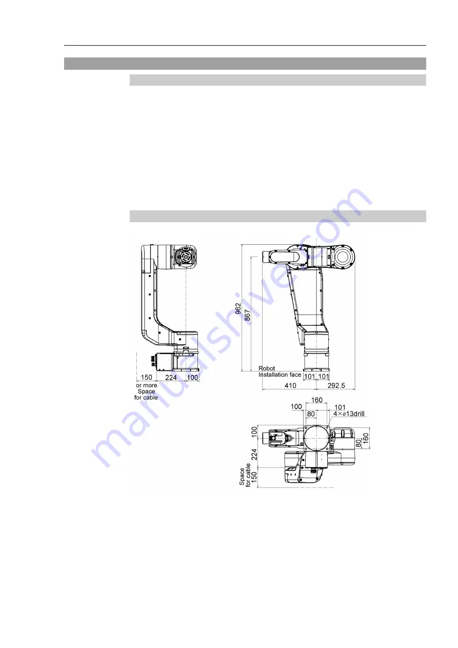
Be sure to have the following space available in addition to the space for mounting the
Manipulator, Controller, and peripheral equipment.
Space for teaching points
Space for maintenance and inspections (for installing jigs)
Space for cables
To prevent the power cable from bending, make sure to leave space for 150mm When
installing the cable, be sure to maintain sufficient distance from obstacles. In addition,
leave enough space for other cables to prevent them from bending.
[Unit: mm]
3.3.2 Mounting dimensions
N6-A1000**: Cable direction: Standard (backward)
NOTE
Summary of Contents for N6 Series
Page 1: ...Rev 2 EM187R3735F 6 Axis Robots N6 series MANIPULATOR MANUAL ...
Page 2: ...Manipulator manual N6 series Rev 2 ...
Page 8: ...vi N6 Rev 2 ...
Page 14: ......
Page 27: ...Setup Operation 1 Safety N6 Rev 2 15 N6 A850 R C A D F G F E H G F B G F G F F F N6 A850 BR F ...
Page 34: ...Setup Operation 2 Specifications 22 N6 Rev 2 N6 A850 BR Cable direction Upward ...
Page 52: ...Setup Operation 3 Environment and Installation 40 N6 Rev 2 N6 A850 R Maximum motion range 802 ...
Page 66: ...Setup Operation 4 End Effectors 54 N6 Rev 2 N6 A850 R Unit mm ...
Page 104: ......
Page 274: ...Maintenance 4 Cable 262 N6 Rev 2 4 7 1 Signal Power cable ...
Page 275: ...Maintenance 4 Cable N6 Rev 2 263 ...
Page 276: ...Maintenance 4 Cable 264 N6 Rev 2 4 7 2 User Cable ...


