Setup & Operation 4. End Effectors
N6 Rev.2
53
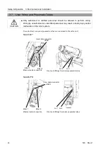
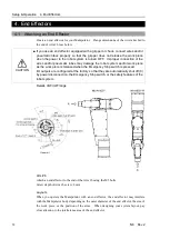
Hole for wires and tubes
When passing wires and tubes through the hole, you need to note the following.
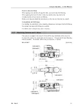
When operating the Joint #5 or the #6, the wires and the tubes may short or be
disconnected due to bent, torsion, and friction.
Make sure to inspect and perform maintenance on the wires and the tubes by yourself.
Compatibility with ISO flange:
For installing the end effector whose mounting dimensions are designed for the ISO flange,
the optional tool adapter (ISO flange) is available.
For details, refer to
Setup & Operation: 6. Options
.
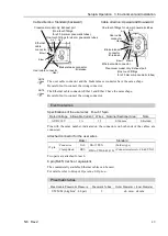
4.2 Attaching Camera and Valves
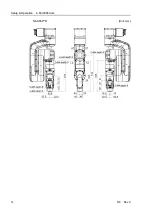
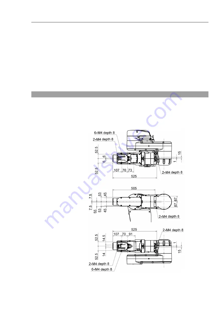
The decks are equipped to the Arms #3, #4 and #5 for easy installation of the air valves.
To mount the camera, the camera plate unit is necessary. The optional Camera Mounting
Plate is available. For details, refer to
Setup & Operation: 6. Options
.
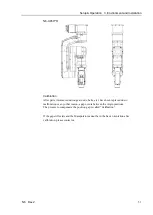
N6-A1000**
[Unit: mm]
Summary of Contents for N6 Series
Page 1: ...Rev 2 EM187R3735F 6 Axis Robots N6 series MANIPULATOR MANUAL ...
Page 2: ...Manipulator manual N6 series Rev 2 ...
Page 8: ...vi N6 Rev 2 ...
Page 14: ......
Page 27: ...Setup Operation 1 Safety N6 Rev 2 15 N6 A850 R C A D F G F E H G F B G F G F F F N6 A850 BR F ...
Page 34: ...Setup Operation 2 Specifications 22 N6 Rev 2 N6 A850 BR Cable direction Upward ...
Page 52: ...Setup Operation 3 Environment and Installation 40 N6 Rev 2 N6 A850 R Maximum motion range 802 ...
Page 66: ...Setup Operation 4 End Effectors 54 N6 Rev 2 N6 A850 R Unit mm ...
Page 104: ......
Page 274: ...Maintenance 4 Cable 262 N6 Rev 2 4 7 1 Signal Power cable ...
Page 275: ...Maintenance 4 Cable N6 Rev 2 263 ...
Page 276: ...Maintenance 4 Cable 264 N6 Rev 2 4 7 2 User Cable ...


