Table of Contents
N6 Rev.2
vii
Setup & Operation
1. Safety
3
1.1 Conventions............................................................................................3
1.2 Design and Installation Safety ................................................................4
1.3 Operation Safety ....................................................................................5
1.4 Emergency Stop .....................................................................................7
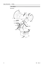
1.5 How to Move Arms with the Electromagnetic Brake ..............................9
Arm Motion ...........................................................................................10
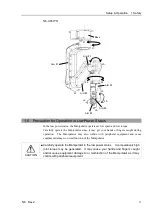
1.6 Precaution for Operation in Low Power Status .................................... 11
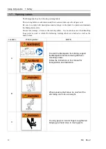
1.7 Warning Labels .....................................................................................12
Location of Labels ................................................................................14
2. Specifications
16
2.1 Model Number ......................................................................................16
2.2 Part Names ...........................................................................................17
2.3 Outer Dimensions .................................................................................20
2.3.1 Basic Orientation ......................................................................20
2.3.2 Orientation with the Maximum Arm Length ..............................23
2.4 Standard Motion Range .......................................................................24
2.5 Specifications .......................................................................................26
2.5.1 Specifications table ..................................................................26
2.5.2 Option .......................................................................................29
2.6 How to Set the Model ...........................................................................29
3. Environment and Installation
30
3.1 Environmental Conditions ....................................................................30
3.2 Unpacking, Transportation, and Relocation .........................................31
3.3 Mounting Dimensions ...........................................................................35
3.3.1 Mounting Area ..........................................................................35
3.3.2 Mounting dimensions ...............................................................35
3.3.3 Motion range .............................................................................37
3.4 Installation ............................................................................................41
3.5 Base Table ............................................................................................44
3.6 Connecting the Cables .........................................................................46
3.7 User Wires and Pneumatic Tubes........................................................48
Electrical wires .....................................................................................49
Pneumatic tubes ..................................................................................49
3.8 Checking the Basic Orientation ............................................................50
4. End Effectors
52
4.1 Attaching an End Effector.....................................................................52
4.2 Attaching Camera and Valves ..............................................................53
4.3 WEIGHT and INERTIA Settings ...........................................................55
4.3.1 WEIGHT setting ........................................................................57
4.3.2 INERTIA setting ........................................................................60
Summary of Contents for N6 Series
Page 1: ...Rev 2 EM187R3735F 6 Axis Robots N6 series MANIPULATOR MANUAL ...
Page 2: ...Manipulator manual N6 series Rev 2 ...
Page 8: ...vi N6 Rev 2 ...
Page 14: ......
Page 27: ...Setup Operation 1 Safety N6 Rev 2 15 N6 A850 R C A D F G F E H G F B G F G F F F N6 A850 BR F ...
Page 34: ...Setup Operation 2 Specifications 22 N6 Rev 2 N6 A850 BR Cable direction Upward ...
Page 52: ...Setup Operation 3 Environment and Installation 40 N6 Rev 2 N6 A850 R Maximum motion range 802 ...
Page 66: ...Setup Operation 4 End Effectors 54 N6 Rev 2 N6 A850 R Unit mm ...
Page 104: ......
Page 274: ...Maintenance 4 Cable 262 N6 Rev 2 4 7 1 Signal Power cable ...
Page 275: ...Maintenance 4 Cable N6 Rev 2 263 ...
Page 276: ...Maintenance 4 Cable 264 N6 Rev 2 4 7 2 User Cable ...


