Setup & Operation 6. Options
N6 Rev.2
81
6. Options
N6 series manipulator has the following options.
6.1 Brake Release Unit
6.2 Camera Plate Unit
6.3 Tool Adapter (ISO flange)
6.4 User Wiring
6.5 M/C cable
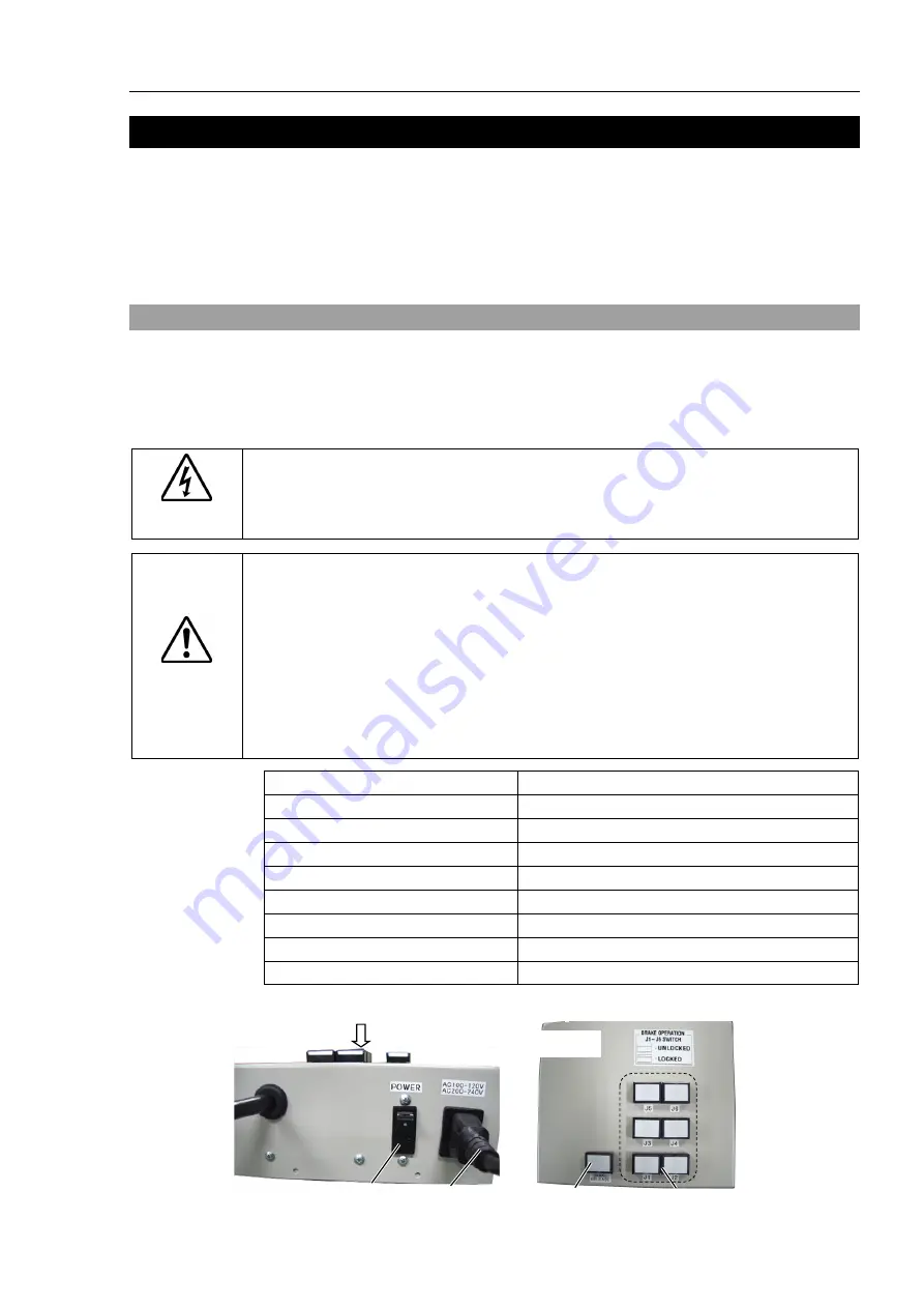
6.1 Brake Release Unit
With the Electromagnetic brakes are ON (such as in Emergency Stop status), all arms
except for the Arm #1 cannot be moved by hand.
You can move the Arms by hand using the brake release unit while the controller power is
OFF or right after unpacking.
WARNING
■
When connecting or replacing the brake release unit and the external short
connector, turn OFF the power to the Controller and the brake release unit.
Connecting and disconnecting the connector while the power is ON may result in
electrical shock.
CAUTION
■
Normally, release the brake of joints one by one. Take extra care if you need to
release the brakes of two or more joints simultaneously. Releasing the brakes
of two or more joints simultaneously may cause hands and fingers to be caught
and/or equipment damage to or malfunction of the Manipulator as the arms of the
Manipulator may move in unexpected directions.
■
Be careful of the arm falling when releasing the brake.
While the brake is being released, the Manipulator’s arm falls by its own weight.
The arm falling may cause hands and fingers to be caught and/or may cause
equipment damage to or malfunction of the Manipulator.
Width
180 mm
Depth
150 mm
Height
87 mm
Weight (Cables are not included.)
1.7 kg
Cable to the Manipulator
2 m
Power cable length
2 m
Power cable (US)
100 V specification
Power cable (EU)
200 V specification
M/C Short connector
For M/C power cable short-circuit
Power cable
Power switch
Arm switches
Power lamp
A
View from A
Summary of Contents for N6 Series
Page 1: ...Rev 2 EM187R3735F 6 Axis Robots N6 series MANIPULATOR MANUAL ...
Page 2: ...Manipulator manual N6 series Rev 2 ...
Page 8: ...vi N6 Rev 2 ...
Page 14: ......
Page 27: ...Setup Operation 1 Safety N6 Rev 2 15 N6 A850 R C A D F G F E H G F B G F G F F F N6 A850 BR F ...
Page 34: ...Setup Operation 2 Specifications 22 N6 Rev 2 N6 A850 BR Cable direction Upward ...
Page 52: ...Setup Operation 3 Environment and Installation 40 N6 Rev 2 N6 A850 R Maximum motion range 802 ...
Page 66: ...Setup Operation 4 End Effectors 54 N6 Rev 2 N6 A850 R Unit mm ...
Page 104: ......
Page 274: ...Maintenance 4 Cable 262 N6 Rev 2 4 7 1 Signal Power cable ...
Page 275: ...Maintenance 4 Cable N6 Rev 2 263 ...
Page 276: ...Maintenance 4 Cable 264 N6 Rev 2 4 7 2 User Cable ...


