EPSON Perfection 4490 Photo
Revision B
Disassembly / Assembly
Disassembly Procedure
40
4.2.6 Removing the Power Switch
1. Move the Carriage Unit to the front of the main unit.
See Section 4.2.3 Step 1 -
Step 3
2. Disconnect the Power Switch Connector CN3 from the Main Board.
See Section
4.2.5 Step 5 - Step 7
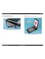
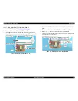
3. Remove the Power Switch Connector Cable from the cable trench.
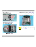
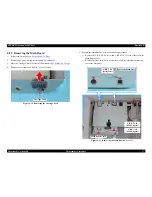
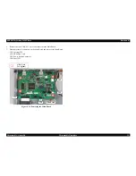
Figure 4-17. Removing the Power Supply Cable Cover
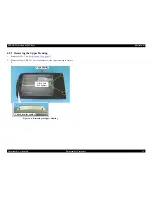
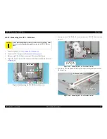
4. Push the Power Switch toward the outside while releasing the two tabs, and
remove the Power Switch by pushing it out through the hole on the Lower
Housing.
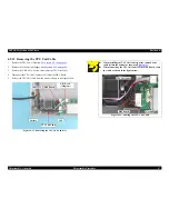
Figure 4-18. Removing the Power Switch
When reinstalling the Power Switch, route the Power Switch
Connector Cable through the cable trench as shown in
Figure
4-17
.
Cable Trench
Power Switch Connector Cable
4-2
Power Switch
Tabs
4-1
4-1
Summary of Contents for Perfection 4490 Photo
Page 8: ...C H A P T E R 1 PRODUCTDESCRIPTION ...
Page 18: ...C H A P T E R 2 OPERATINGPRINCIPLES ...
Page 25: ...C H A P T E R 3 TROUBLESHOOTING ...
Page 29: ...C H A P T E R 4 DISASSEMBLY ASSEMBLY ...
Page 57: ...C H A P T E R 5 ADJUSTMENT ...
Page 59: ...C H A P T E R 6 MAINTENANCE ...
Page 63: ...C H A P T E R 7 APPENDIX ...
Page 66: ...Model GT X750 Perfection 4490 Photo Board Main Board Rev A Sheet 1 1 ...
Page 68: ...Model GT X750 Perfection 4490 Photo Board DRV Board Assy Rev A Sheet 1 1 ...
Page 69: ...Model GT X750 Perfection 4490 Photo Board Image Sensor Board Rev B Sheet 1 1 ...
Page 70: ...Model GT X750 Perfection 4490 Photo Board SUB Board Rev A Sheet 1 1 ...
Page 71: ...Model GT X750 Perfection 4490 Photo Board SUB C Board Rev A Sheet 1 1 ...
Page 72: ...Model GT X750 Perfection 4490 Photo Board SUB D Board Rev A Sheet 1 1 ...
Page 74: ...GT X750 Perfection 4490 Photo NO 1 Rev 02 B176 ACCE 0012 10 20 30 40 400 401 ...
Page 76: ...R ev 01 B176 CAS E 002 GT X750 Perfection 4490 Photo NO 3 110 111 101 102 ...


