EPSON Perfection 4490 Photo
Revision B
Disassembly / Assembly
Disassembly Procedure
44
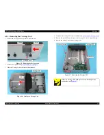
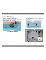
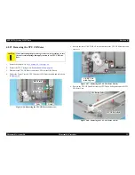
3. Remove the torsion spring and the C.B. M3 x 3 screw that secure the Tensioner,
and remove the Pulley.
4. Remove the Motor Tension Belt and the CR Tension Belt from the CR Motor Unit
in that order.
Figure 4-25. Removing the Motor Tension Belt and the CR Tension Belt
A D J U S T M E N T
R E Q U I R E D
When installing the Tensioner, make sure to perform the Tensioner
Adjustment.
See Section 5.1.2.1 on page 58.
Torsion Spring
Tensioner
Pulley
Motor Tension Belt
CR Tension Belt
C.B. 3 x 3
(6±1kgf.cm)
Summary of Contents for Perfection 4490 Photo
Page 8: ...C H A P T E R 1 PRODUCTDESCRIPTION ...
Page 18: ...C H A P T E R 2 OPERATINGPRINCIPLES ...
Page 25: ...C H A P T E R 3 TROUBLESHOOTING ...
Page 29: ...C H A P T E R 4 DISASSEMBLY ASSEMBLY ...
Page 57: ...C H A P T E R 5 ADJUSTMENT ...
Page 59: ...C H A P T E R 6 MAINTENANCE ...
Page 63: ...C H A P T E R 7 APPENDIX ...
Page 66: ...Model GT X750 Perfection 4490 Photo Board Main Board Rev A Sheet 1 1 ...
Page 68: ...Model GT X750 Perfection 4490 Photo Board DRV Board Assy Rev A Sheet 1 1 ...
Page 69: ...Model GT X750 Perfection 4490 Photo Board Image Sensor Board Rev B Sheet 1 1 ...
Page 70: ...Model GT X750 Perfection 4490 Photo Board SUB Board Rev A Sheet 1 1 ...
Page 71: ...Model GT X750 Perfection 4490 Photo Board SUB C Board Rev A Sheet 1 1 ...
Page 72: ...Model GT X750 Perfection 4490 Photo Board SUB D Board Rev A Sheet 1 1 ...
Page 74: ...GT X750 Perfection 4490 Photo NO 1 Rev 02 B176 ACCE 0012 10 20 30 40 400 401 ...
Page 76: ...R ev 01 B176 CAS E 002 GT X750 Perfection 4490 Photo NO 3 110 111 101 102 ...

