background image

PRECAUTIONS

Precautionary notations throughout the text are categorized relative to 1) Personal injury and 2) damage to equipment.

DANGER

Signals a precaution which, if ignored, could result in serious or fatal personal injury. Great caution should be exercised in performing procedures preceded by 
DANGER Headings.

WARNING

Signals a precaution which, if ignored, could result in damage to equipment.

The precautionary measures itemized below should always be observed when performing repair/maintenance procedures.

DANGER

1.

ALWAYS DISCONNECT THE PRODUCT FROM THE POWER SOURCE AND PERIPHERAL DEVICES PERFORMING ANY MAINTENANCE OR REPAIR PROCEDURES.

2.

NO WORK SHOULD BE PERFORMED ON THE UNIT BY PERSONS UNFAMILIAR WITH BASIC SAFETY MEASURES AS DICTATED FOR ALL ELECTRONICS 
TECHNICIANS IN THEIR LINE OF WORK.

3.

WHEN PERFORMING TESTING AS DICTATED WITHIN THIS MANUAL, DO NOT CONNECT THE UNIT TO A POWER SOURCE UNTIL INSTRUCTED TO DO SO. WHEN 
THE POWER SUPPLY CABLE MUST BE CONNECTED, USE EXTREME CAUTION IN WORKING ON POWER SUPPLY AND OTHER ELECTRONIC COMPONENTS.

4.

WHEN DISASSEMBLING OR ASSEMBLING A PRODUCT, MAKE SURE TO WEAR GLOVES TO AVOID INJURIER FROM METAL PARTS WITH SHARP EDGES.

WARNING

1. REPAIRS ON EPSON PRODUCT SHOULD BE PERFORMED ONLY BY AN EPSON CERTIFIED REPAIR TECHNICIAN.

2.

MAKE CERTAIN THAT THE SOURCE VOLTAGES IS THE SAME AS THE RATED VOLTAGE, LISTED ON THE SERIAL NUMBER/RATING PLATE. IF THE EPSON 
PRODUCT HAS A PRIMARY AC RATING DIFFERENT FROM AVAILABLE POWER SOURCE, DO NOT CONNECT IT TO THE POWER SOURCE.

3.

ALWAYS VERIFY THAT THE EPSON PRODUCT HAS BEEN DISCONNECTED FROM THE POWER SOURCE BEFORE REMOVING OR REPLACING PRINTED CIRCUIT 
BOARDS AND/OR INDIVIDUAL CHIPS.

4.

IN ORDER TO PROTECT SENSITIVE MICROPROCESSORS AND CIRCUITRY, USE STATIC DISCHARGE EQUIPMENT, SUCH AS ANTI-STATIC WRIST STRAPS, WHEN 
ACCESSING INTERNAL COMPONENTS.

5.

DO NOT REPLACE IMPERFECTLY FUNCTIONING COMPONENTS WITH COMPONENTS WHICH ARE NOT MANUFACTURED BY EPSON. IF SECOND SOURCE IC OR 
OTHER COMPONENTS WHICH HAVE NOT BEEN APPROVED ARE USED, THEY COULD CAUSE DAMAGE TO THE EPSON PRODUCT, OR COULD VOID THE 
WARRANTY OFFERED BY EPSON.

Summary of Contents for Perfection 4870 Photo

Page 1: ...EPSON Perfection4870Photo Color Image Scanner Service Manual SESC03 008 ...

Page 2: ...d greatly appreciate being informed of them The contents of this manual are subject to change without notice The above not withstanding SEIKO EPSON CORPORATION can assume no responsibility for any errors in this manual or the consequences thereof EPSON is a registered trademark of SEIKO EPSON CORPORATION General Notice Other product names used herein are for identification purpose only and may be ...

Page 3: ...E MUST BE CONNECTED USE EXTREME CAUTION IN WORKING ON POWER SUPPLY AND OTHER ELECTRONIC COMPONENTS 4 WHEN DISASSEMBLING OR ASSEMBLING A PRODUCT MAKE SURE TO WEAR GLOVES TO AVOID INJURIER FROM METAL PARTS WITH SHARP EDGES WARNING 1 REPAIRS ON EPSON PRODUCT SHOULD BE PERFORMED ONLY BY AN EPSON CERTIFIED REPAIR TECHNICIAN 2 MAKE CERTAIN THAT THE SOURCE VOLTAGES IS THE SAME AS THE RATED VOLTAGE LISTED...

Page 4: ...Electric circuit boards components layout Electrical circuit boards schematics Exploded diagram Parts List Symbols Used in this Manual Various symbols are used throughout this manual either to provide additional information on a specific topic or to warn of possible danger present during a procedure or an action Be aware of all symbols when they are used and always read NOTE CAUTION or WARNING mes...

Page 5: ...Revision Status Revision Date of Issue Description A December 10 2003 First release ...

Page 6: ... 4 1 Power Supply Circuit operation outline 27 2 4 2 Image processing operation 28 Chapter 3 TROUBLESHOOTING 3 1 Overview 30 3 1 1 Self diagnostic Function 30 3 2 Troubleshooting 31 Chapter 4 DISASSEMBLY ASSEMBLY 4 1 Overview 38 4 1 1 Precautions 38 4 1 2 Recommended Tools 38 4 1 3 The List of Recommended Screws 39 4 2 Disassembly Procedure 40 4 2 1 Removal of Document Cover 41 4 2 2 Removal of Up...

Page 7: ...r 6 MAINTENANCE 6 1 Overview 66 6 1 1 Cleaning 66 6 1 2 Lubrication 67 Chapter 7 APPENDIX 7 1 Connector Configuration 69 7 1 1 Connector Configuration 69 7 1 2 Connector Connection Table 69 7 2 Circuit Diagrams 70 7 3 Exploded diagram 82 7 4 Service Parts List 86 ...

Page 8: ...C H A P T E R 1 PRODUCTDESCRIPTION ...

Page 9: ... operation EPSON Smart Panel 3 0 Scan to PDA and PDF support Achieved easy scanning with a start button Ease of exporting image data to an application Monochrome negative film support PRINT Image Matching 2 support EPSON Scan Graphic user interface Full Mode Home Mode and Professional Mode In addition to the functions of the TWAIN driver Image data can be saved as a standalone application without ...

Page 10: ...n Gamma Correction Output by output correction Standard 5 level CRT 2 level A B PRINTER 3 level A B C User defined 1 level Color Correction Output by output correction Standard 4 level Impact Dot Printer Thermal Printer Ink Jet Printer CRT Display User defined Brightness 7 levels Data processing Bi level Error Diffusion 3 mode A B C Dither Resident 4 mode A B C D TET AAS Quad level Error Diffusion...

Page 11: ...by the vender of the Host 4 Microsoft USB2 0 driver is necessary 5 For standard equipped by Pre install PC or upgraded PC from Windows 2000 Professional model only 6 EPSON Scan EPSON driver SilverFast works independently or only with Adobe Photoshop 7 0 on Mac OS X native mode Some applications and or functions only work in Mac OS X classic mode LID TYPE TPU BASIC SPECIFICATION Type Moving carriag...

Page 12: ...rt15 Subpart B Class B CSA C108 8 200V system EN60950 IEC60950 EN55022 Class B EN61000 3 2 EN61000 3 3 EN55024 AS NZS 3548 Class B CISPR Pub22 Class B Environment protection International Energy Star Program ELECTRICAL NOISE RESISTANCE Static electricity Contact discharge 4 5kV Air discharge 8 5kV ENVIRONMENTAL CONDITIONS Temperature Operating 5 C to 35 C Storage 25 C to 60 C Humidity Operating 10...

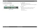
Page 13: ...low Figure 1 1 Interface 1 3 1 IEEE1394 In compliance with IEEE Std 1394a 2000 In compliance with ANSI X3T10 Serial Bus Protocol 2 Revision4L SBP 2 6 pin connector x 1 1 3 2 USB In compliance with Universal Serial Bus specification Revision 2 0 Hi speed device 480Mbps Full speed capable 12Mbps Self powered Standard B connector x 1 IEEE1394 USB2 0 OPTION ...

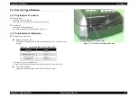
Page 14: ...nation of indications Status LED green red Lit flashing or extinguished to indicate the Ready Busy or Error status of the scanner 1 Warm up scan initialization etc 2 May not be lit red depending on the error option error command error TPU lamp LED blue Lights up in synchronization with ON OFF of the TPU lamp Figure 1 2 Locations of Switches and LEDs Table 1 1 Statuses and Indications of Status LED...

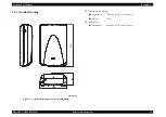
Page 15: ...IPTION Exterior Specifications 15 1 4 3 Outside Drawing Figure 1 3 Outside Drawing of Perfection 4870 Photo Dimensions and Weight Dimensions 304 W x 476 D x 134 H mm Weight 6 7kg Package size Dimensions 405 W x 573 D x 230 H mm 476 134 304 Unit mm ...

Page 16: ... ESC C i Mirroring setting ESC K i Scanning parameter setting FS W Correction processing Brightness correction setting ESC L i Gamma correction setting ESC Z i Gamma correction table setting ESC z i d 256 Sharpness control setting ESC Q i Image processing Halftone process setting ESC B i Auto area segmentation setting ESC s i Dither pattern setting ESC b i j d j 2 Color correction setting ESC M i ...

Page 17: ... The scanner ignores the incorrect command or parameter Current setting maintained The scanner returns NACK and waits for the next command parameter The error condition is cleared when the scanner receives a correct command Fatal error Red LED flashes in sort interval The lamp is dead The main unit is faulty Firmware downloading failed Turn the lamp off and stop the operation Set Bit 7 of the stat...

Page 18: ...ze 216 x 297mm horizontal x vertical Figure 1 4 Reflective Document Scanning Range 1 7 2 Transparent document Size 144 x 231mm horizontal x vertical Figure 1 5 Transparent Document Scanning Range 216mm 1 0 0 5mm 1 0 0 5mm 297mm Scanning home position Front 144mm 37 9 1 5mm 21 6 1 5mm 231mm Scanning home position Front ...

Page 19: ...C H A P T E R 2 OPERATINGPRINCIPLES ...

Page 20: ...ode fluorescent lamps Lamps White cool cathode fluorescent lamps are used as a light source When the amount of light is not stable the Panel LED is flashes and enter the standby mode until it becomes stable Mirror Lens Mechanism The beam applied to the scanned document is reflected passes through the Mirror Lens Mechanism in the Carriage Unit for correction of the beam axis and then reaches the CC...

Page 21: ...iguration TPU Inverter Board Boosts 24VDC and converts DC to AC to generate the voltage for driving the Lamps white cool cathode fluorescent lamps Lamps White cool cathode fluorescent lamps are used as a light source When the amount of light is not stable the Panel LED is flashes and enter the standby mode until it becomes stable SUB_C Board Each board has LEDs to generate an infrared light SUB_D ...

Page 22: ...ent to the Control Board The scanning of Line n data and the processing of Line n 1 image data are performed consecutively at the same time Figure 2 4 Carriage Movement The Carriage Unit slides along the guide rail in the sub scanning direction To perform this sliding operation the CR Carriage Motor transmits its drive power to the CR Timing Belt which is fixed to the Carriage Unit via the Drive P...

Page 23: ... this sliding operation the TPU CR Carriage Motor transmits its drive power to the TPU CR Timing Belt which is fixed to the Carriage Unit via the Drive Pulley and the Deceleration Gear The TPU CR Motor uses a stepping motor and is driven under open loop control Refer to figure 2 6 Figure 2 6 TPU Carriage Operation Front Rear TPU Carriage Unit Driven Pulley TPU CR Timing Belt TPU CR Motor Decelerat...

Page 24: ...p and determines the inconsistent portion as a flaw or dust 4 Erases the portion on the hardware which has been detected in the step 3 and obtains the image without any flaw and or dust 2 2 2 Film Ice function Film Ice function outline Longer in wavelength than a visible light an infrared light has a property that it scans a transparent document transparently Hence when a document with dust and or...

Page 25: ...using Scale section 2 Scan a visible light image 3 Scan an infrared light image 4 Superimposes the images obtained from each light and detects the flaws and or the foreign matter 5 Erases the flaws and or the foreign matter on the hardware which have been detected in the step 4 and obtains the image without any flaw and or foreign matter Figure 2 8 Extraction Correction of Dust by Film Ice Functio...

Page 26: ...cessary for recovery is 5 minutes maximum Table 2 1 Destination based Power Supply Circuit Boards Specifications Unit Part No Fuse Rating 100 120VAC region 2027705 2 5 A 125 VAC 220 240VAC region 2027704 T2 5AH 250 VAC Table 2 2 Power Supply Circuit Board Outputs and Protective Functions Output Voltage Output Current Overcurrent Protection Protective circuit operation current value Overvoltage Pro...

Page 27: ...tion IC Location IC IC1 A3957SLB ATR IC8 ISP1581BD GX IC2 A3957SLB ATR IC9 K4S561632D TC75000 IC3 AT93C46 10SI 1 8 IC10 74LVC138AD IC4 UPC37M32 IC11 S80927CLMCGGX IC5 E01A23EB IC12 74LVC02AD IC6 MR27V402EJA IC13 K4S561632D TC75000 IC7 AS7C31025 15TJC IC14 TSB43AA82APGE Table 2 4 IC Explanation Location IC Location IC IC1 ILX183K IC5 NJU7665CF TE1 IC2 BA178M05FP E2 IC6 74HCT4053PW IC3 AD9826KRS REE...

Page 28: ... Amplification processing 2 Main Board Scanned image data processing A D conversion processing scanned image data generated as an analog electric signal is converted to a digital signal Shading correction processing scanned image data is corrected on the basis of the white and black reference values Various image correction processing gamma correction color correction halftone correction etc are e...

Page 29: ...C H A P T E R 3 TROUBLESHOOTING ...

Page 30: ...remedies are as described below COMMAND ERROR FATAL ERROR Table 3 1 Command Error LED Indication Cause Corrective Action An undefined command or undefined command parameter was received The scanner ignores the incorrect command or parameter Current setting maintained The scanner returns NACK and waits for the next command parameter Recover The error status is canceled on receipt of a correct comma...

Page 31: ... Fluorescent Lamps are not lit Connector Fluorescent Lamps Carriage Main Board 3 3 Scanned image quality error An image cannot be scanned clearly Smudge on Document Glass Smudge on Mirror Sheet White Section CCD Board Main Board 3 4 Occurrence of Communication error The LED flashes red After occurrence of the above error Communication error occurs when communication is made with the host again The...

Page 32: ...d Has the fuse of the power supply blown out Replace the Power Supply Board Replace the CR Motor Replace the Power Supply Board Has the Carriage Lock been released Is the Carriage Moving Mechanism without problem Start Release the Carriage Lock Replace the CR Motor Can the CR Motor operate normally Is the Housing Upper installed correctly Install it normally Is the Connector CN6 on the Main Board ...

Page 33: ... the Harness Connect the Connector Connect the Connectors Re set them on the Inverter Board Replace the Main Board Is the Document Glass free from smudge etc Is the Sheet White Section free from smudge distortion etc Is the CCD Sensor Board normal Start Remove smudge Refer to Chapter 6 6 1 1Cleaning Is the scanned image without problem Image has white spots Are the Mirrors in the Carriage free fro...

Page 34: ...Cable normal Has USB been made valid after choosing My Computer Properties Device Manager on Windows Start Replace the host Install reinstall the TWAIN Driver for Perfection 4870 Photo Replace the Cable Replace the Main Board Is the TPU Cable on the rear of the scanner connected securely Is the Connector CN8 of the Main Board connected Is the TPU Main Board normal 24V line Lamp Motor 5V line Senso...

Page 35: ...ected Are the Fluorescent Lamps set on the TPU Inverter Board securely Is the TPU Harness connected to the TPU Main Board and TPU Carriage Start Connect the TPU Harness Connect the Connector Connect the Connector Re setthem on the TPU Inverter Board Replace the TPU Main Board Has the TPU Carriage Lock been released Start Release the TPU Carriage Lock Replace the TPU CR Motor Can the TPU CR Motor o...

Page 36: ...oes not light up Is the TPU Harnessconnected to the TPU Main Board and TPU Carriage Is the Connector CN2 connected to the TPU Main Board Are the Connectors CN2 CN3 on the TPU Inverter Board connected Start Connect the TPU Harness Connect the Connector Connect the Connectors Replace the SUB_C D Board ...

Page 37: ...C H A P T E R 4 DISASSEMBLY ASSEMBLY ...

Page 38: ...re disassembling or reassembling this product always disconnect the Power Cable and Interface Cable However when you have to work with power ON for voltage measurement etc use extreme care not to get an electric shock and do the work in accordance with the procedure given in this manual To prevent your hands from being cut by sharp edges always wear gloves before starting disassembly reassembly Wh...

Page 39: ...rews used in the Perfection 4870 Photo Table 4 2 The List of Recommended Screws No Standard Outline 1 C B P M3x6 Bind P tite Screw 2 C B P M3x8 Bind P tite Screw 3 C B P M3x12 Bind P tite Screw 4 C B P M4x12 Bind P tite Screw 5 C B S M3x5 Bind S tite Screw 6 C C P M3x6 Cup P tite Screw 7 C P M3x4 Pan Head Screw 8 C B M3x3 Bind Screw 9 6N 5 ...

Page 40: ...o the corresponding page number shown in the following figure Figure 4 2 Disassembly Assembly Flowchart Start Removal of Document Cover P 41 Removal of Upper Housing P 42 Removal of Panel Board P 43 Removal of Main Board P 44 Removal of Carriage Unit P 46 Removal of SUB_A Board P 50 Removal of Power Supply Cable Unit P 52 Removal of CR Motor Unit P 48 Removal of Driven Pulley P 49 Removal of TPU L...

Page 41: ...sconnect the TPU Unit Connector on the rear side of the Main Unit Figure 4 3 Disconnection of TPU Unit Connector 2 Open the Document Cover Figure 4 4 Removal of Document Cover 1 3 Hold both ends of the Document Cover and then lift and remove it Figure 4 5 Removal of Document Cover 2 TPU Unit Connector Document Cover ...

Page 42: ...ure 4 6 Releasing of Carriage Lock 3 Remove the two screws C B P M3x8 which secure the Upper Housing Figure 4 7 Removal of Upper Housing 1 4 Lift the rear side of the Upper Housing slide it to the front release the three hooks and remove the Upper Housing Figure 4 8 Removal of Upper Housing 2 5 Disconnect the SW Connector from the SUB_A Board Figure 4 9 Removal of Upper Housing 3 C B P M3x8 7 1 kg...

Page 43: ...el Board and then remove it Figure 4 10 Removal of Panel Board Route the SW Connector Cable by passing it through the notches of the Upper Housing as shown in Figure 4 10 After installing the Function Button on the Panel Board in the orientation shown in Figure 4 11 install the Panel Board on the Upper Housing Figure 4 11 Installation of Function Button Notches SW Connector Cable Panel Board C B P...

Page 44: ...Remove the two screws C B S M3x5 which secure the Main Board Cover 4 Remove the Main Board Cover in the following procedure 1 Release the hook A and the hook B and lift the rear side of the Main Board Cover 2 With the Main Board Cover lifted slide it to the rear release the hook C and then remove the Main Board Cover Figure 4 13 Removal of Main Board Cover Carriage Unit Hook C Step 4 2 Hook A C B ...

Page 45: ...n remove the Main Board Figure 4 14 Removal of Main Board Carriage FFC Power Supply Board Connector C B S M3x5 9 1 kgfcm CR Motor Connector Main Board Main Unit rear C P M3x4 4 1 kgfcm Pass the Carriage FFC through the Ferrite Core and adhere it with a two sided tape at the position shown in Figure 4 15 Figure 4 15 Installation of Carriage FFC Pass the CR Motor Cable under the Shaft Holder as show...

Page 46: ... the Carriage Shaft until its flat surfaces match the notch Figure 4 18 Removal of Carriage Shaft 2 5 While lifting the Carriage Unit as shown in Figure 4 19 remove the rear part of the Carriage Shaft from the notch and pull the front part out of the Bushing 6 Pull the Carriage Shaft out of the Carriage Unit Figure 4 19 Removal of Carriage Shaft 3 7 Lift the Carriage Unit remove the lock plate and...

Page 47: ...the Carriage FFC from the Main Board Refer to Step 3 to Step 5 in 4 2 4 Removal of Main Board 9 Remove the Carriage FFC from the Base Frame and then remove the Carriage Unit Pass the Carriage FFC through the Ferrite Core and adhere it with a two sided tape at the position shown in Figure 4 15 ...

Page 48: ...Figure 4 22 Removal of CR Timing Belt 4 Disconnect the CR Motor Connector from the Main Board 5 Remove the CR Motor Cable from the Base Frame and then remove the CR Motor Unit Figure 4 23 Removal of CR Motor Cable Install the CR Motor Unit by matching the positioning holes and the bosses as shown in Figure 4 21 CR Motor Unit Positioning hole and boss Positioning holes and bosses C B S M3x5 9 1 kgf...

Page 49: ...3x3 which secures the Driven Pulley Unit and then remove the Driven Pulley Unit Figure 4 24 Removal of Driven Pulley Unit 3 Remove the E ring and then remove the Driven Pulley Figure 4 25 Removal of Driven Pulley C B M3x3 9 1 kgfcm Driven Pulley Unit E ring Driven Pulley Holder E ring Driven Pulley Torsion Spring Get the ends of the Torsion Spring caught in the two hooks as shown in Figure 4 26 Fi...

Page 50: ...M3x8 which secure the Base Frame 3 Disconnect the SUB_A Board Connector from the Power Supply Board Figure 4 27 Screws Securing Base Frame 4 While lifting the front part of the Base Frame remove the screw C B S M3x5 and two hooks which secure the SUB_A Board and then remove the SUB_A Board Figure 4 28 Removal of SUB_A Board C B P M3x8 7 1 kgfcm Base Frame SUB_A Board Connector Hooks C B S M3x5 9 1...

Page 51: ...e Power Supply Board Unit release the five hooks on the right side and then remove the Power Supply Board Unit Figure 4 30 Removal of Power Supply Board Unit 2 5 Disconnect the Main Board Connector from the Power Supply Board 6 Remove the five screws C B S M3x5 which secure the Power Supply Board and then remove the Power Supply Board from the Power Supply Board Cover Figure 4 31 Removal of Power ...

Page 52: ... three screws C B S M3x5 which secure the Power Supply Cable Unit Figure 4 32 Removal of Power Supply Cable Unit 1 6 Release the two hooks and then remove the Power Supply Cable Unit Figure 4 33 Removal of Power Supply Cable Unit 2 Adhere the Power Supply Cover to the Lower Housing with a two sided tape at the position shown in Figure 4 32 Tighten together the screws shown in Figure 4 32 which sec...

Page 53: ...ocument Cover 2 Release the TPU Carriage Lock Figure 4 34 Releasing TPU Carriage Lock 3 Remove the seven screws C B P M3x12 which secure the TPU Lower Housing 4 By inserting a flat blade screwdriver release the eight hooks which secure the TPU Lower Housing and then remove the TPU Lower Housing Figure 4 35 Removal of TPU Lower Housing C B P M3x12 5 1 kgfcm Hooks Hooks ...

Page 54: ... the TPU Carriage FFC from the TPU Main Board Figure 4 37 Disconnection of TPU Carriage FFC 4 While setting up the TPU Carriage Unit vertically disconnect all the connectors and the TPU Carriage FFC on the TPU Inverter Board 5 Remove the two screws C C P M3x6 which secure the Inverter Board Unit and then remove the TPU Inverter Board Unit Figure 4 38 Removal of TPU Inverter Unit C B P M3x6 5 1 kgf...

Page 55: ...eet and remove the Inverter Board Figure 4 39 Removal of TPU Inverter Board When reconnecting the connectors and the FFC route the cables by passing them through the notches as shown in Figure 4 40 Figure 4 40 Routing of FFC and Connector Cables TPU Inverter Board Protective Sheet Notches Notches Notches ...

Page 56: ...t pull the TPU CR Timing Belt out of the hook Figure 4 42 Removal of TPU CR Timing Belt 4 Remove the TPU Carriage Shaft from the Bushing on the rear of the TPU Upper Housing and while supporting the TPU Carriage Unit by hand remove the TPU Carriage Shaft from the Bushing on the front of the TPU Lower Housing 5 Pull out the TPU Carriage Shaft and then remove the TPU Carriage Unit Figure 4 43 Remova...

Page 57: ... Carriage FFC from the TPU Main Board Refer to Step 2 to Step 3 in 4 2 12 Removal of TPU Inverter Board 4 Disconnect the three connectors from the TPU Main Board 5 Remove the two screws C B P M3x8 which secure the TPU Main Board Unit 6 Remove the TPU Main Board Cover and then remove the TPU Main Board Figure 4 45 Removal of TPU Main Board TPU Carriage Unit Connectors TPU Main Board Unit Positionin...

Page 58: ...n remove the Hinges Figure 4 47 Removal of Hinges When reinstalling the TPU Main Board and the TPU Main Board Cover match the positioning holes and the bosses as shown in Figure 4 45 Put the recessed part of the TPU Main Board Cover under the Shield Plate and tighten it together with the Shield Plate Figure 4 46 Tightening Together With Shield Plate and Cover Shield Plate Shield Plate TPU Main Boa...

Page 59: ...1 Remove the Hinge Right Refer to 4 2 15 Removal of Hinges 2 Disconnect the TPU CR Motor Connector from the TPU Main Board Figure 4 50 Disconnection of TPU CR Motor Connector Route the SUB_B Board Cable by passing it into the notches as shown in Figure 4 49 Figure 4 49 Routing of SUB_B Board Cable SUB_B Board SUB_B Board Connector Notches SUB_B Board Cable Notches Route the TPU CR Motor Cable by p...

Page 60: ...d the Driven Pulley and then remove the TPU CR Motor Belt Figure 4 53 Removal of TPU CR Motor Belt When reinstalling the TPU CR Motor Unit match the positioning holes and the bosses as shown in Figure 4 52 C B P M3x8 5 1 kgfcm C B P M3x8 5 1 kgfcm TPU CR Timing Belt TPU CR Motor Unit Positioning holes and the bosses Loop the TPU CR Motor Belt over the Idle Pulley and the Pinion Gear of the TPU CR ...

Page 61: ...the two screws C B P M3x8 which secure the TPU Driven Pulley Unit and then remove the TPU Driven Pulley Unit Figure 4 55 Removal of TPU Driven Pulley Unit 4 Pull the TPU CR Timing Belt out of the hook of the TPU Carriage Unit and then remove the TPU CR Timing Belt Figure 4 56 Removal of TPU CR Timing Belt When reinstalling the TPU Driven Pulley Unit match the positioning holes and the bosses as sh...

Page 62: ...able 1 Remove the Hinge Right Refer to 4 2 15 Removal of Hinges 2 Disconnect the TPU Unit Connector from the TPU Main Board Figure 4 57 Removal of TPU Unit Cable Route the TPU Unit Cable by passing it through the notches as shown in Figure 4 58 Figure 4 58 Routing of TPU Unit Cable TPU Unit Connector Notches ...

Page 63: ...C H A P T E R 5 ADJUSTMENT ...

Page 64: ...Perfection 4870 Photo Revision A ADJUSTMENT 64 This product does not require any adjustment in the range of the disassembly and reassembly explained in Chapter 4 ...

Page 65: ...C H A P T E R 6 MAINTENANCE ...

Page 66: ... of it wipe the exterior with that close If the exterior is extremely dirty wipe it with a cloth moistened with a small amount of detergent Document Glass Clean it with a clean dry cloth When the Document Glass is especially dirty or has foreign matter on its surface wipe it with a cloth moistened with a small amount of pure water If the Document Glass has traces of wiping after cleaning completel...

Page 67: ...ication points are shown in Figure 6 1 Table 6 1 Specified Grease Figure 6 1 Lubrication Points Type Name Part Number Supplier Grease G 26 1080614 EPSON Lubrication point Shaft Oil type G 26 Amount of application A little Shaft Driven Pulley Holder Lubrication point Shaft Oil type G 26 Amount of application A little C A U T I O N Note that a failure to strictly observe the specified amount of appl...

Page 68: ...C H A P T E R 7 APPENDIX ...

Page 69: ...CN1 IEEE 1394 8 CN2 USB 4 CN5 CCD Board 29 CN6 CR Motor 4 CN7 Power Supply Board 15 CN8 TPU Inverter Board 8 Power Supply Board CN1 AC Input 2 CN101 Main Board 15 CN102 SUB_A Board 6 SUB_A Board CN1 Panel Board 4 CN2 Power Supply Board 6 Panel Board CN1 SUB_A Board 4 CCD Board CN1 Main Board 29 CN2 Inverter Board 4 CN3 Sensor 2 Inverter Board CN1 CCD Board 4 CN2 Lamp 2 CN3 Lamp 2 TPU Main Board CN...

Page 70: ...70 7 2 Circuit Diagrams The control electrical circuit diagrams of this product are shown on the following pages Main Board Power Supply Board SUB_A Board Panel Board CCD Board Inverter Board TPU Main Board SUB_B Board TPU Inverter Board SUB_C Board SUB_D Board ...

Page 71: ......

Page 72: ......

Page 73: ......

Page 74: ......

Page 75: ......

Page 76: ......

Page 77: ......

Page 78: ......

Page 79: ......

Page 80: ......

Page 81: ......

Page 82: ...sion A APPENDIX Exploded diagram 82 7 3 Exploded diagram Figure 7 2 Exploded diagram 1 GT X700 PERFECTION 4870 PHOTO 4870 PRO NO 1 Rev 01 B163 ACCE 011 402 for 220V Harness socket for 100V models 10 12 410 400 401 14 13 15 11 16 ...

Page 83: ...ion A APPENDIX Exploded diagram 83 Figure 7 3 Exploded diagram 2 115 118 114 104 113 125 122 122 116 117 302 101 121 100 125 124 123 111 119 109 110 103 102 129 130 GT X700 PERFECTION 4870 PHOTO 4870 PRO NO 2 Rev 01 B163 CASE 011 ...

Page 84: ...A APPENDIX Exploded diagram 84 Figure 7 4 Exploded diagram 3 144 146 147 148 145 304 307 140 141 143 303 134 305 306 107 106 149 135 136 137 138 139 150 131 132 133 GT X700 PERFECTION 4870 PHOTO 4870 PRO NO 3 Rev 01 B163 CASE 021 A A ...

Page 85: ...hoto Revision A APPENDIX Exploded diagram 85 Figure 7 5 Exploded diagram 4 520 GT X700 PERFECTION 4870 PHOTO 4870 PRO NO 4 Rev 01 B163 MECH 011 502 507 512 513 521 524 511 510 501 523 301 506 505 504 508 500 522 300 200 ...

Page 86: ...FRONT B 113 LEVER MOUNT CARRIAGE 114 CUSHION 160X5 115 SHEET DUST COVER 116 CUSHION 45X6 117 SHEET COVER 35 118 HOLDER FSW BOARD 119 HINGE SET 121 FOOT 122 C B P SCREW 4X12 F ZN 123 HARNESS TPU 124 LOGO PLATE 125 FOOT 129 LEVER LOCK 130 TPU ASSY Lid ASP 131 CARRIAGE TPU ASP 132 CHIP SLIDER 133 COVER BOARD ASSY INVERTOR 134 REFLECTOR TPU 135 REFLECTOR LAMP TPU B 136 REFLECTOR LAMP TPU C 137 LAMP AS...

Page 87: ... 501 MOTOR ASSY ASP 502 CARRIAGE ASSY ASP 504 FERRITE CORE 505 TORSION SPRING 506 PULLEY DRIVEN 507 FERRITE CORE 508 HARNESS MOTOR 510 FOAM DUSTPROOF B 511 FOAM DUSTPROOF 512 RETAINING RING B150300711 513 CLAMP TIMING BELT 520 SHEET SLIDE 521 HARNESS PS 522 SHEET P S BOARD 523 SUPPORT P SW 524 COVER COVER INLET NON FIG OTPROM BLANK Table 7 2 Perfection 4870 Photo Parts List Ref No Part Name ...

Reviews: