EPSON Perfection 640U
RevIsion A
Operating Principles
Engine Mechanism
16
2.1 Engine Mechanism
This section explains the engine functions and operating principles of the
EPSON Perfection 640U. The engine mechanism has the two major parts; the
carriage unit (=scanning head) and the carriage move mechanism.
2.1.1 Carriage Unit
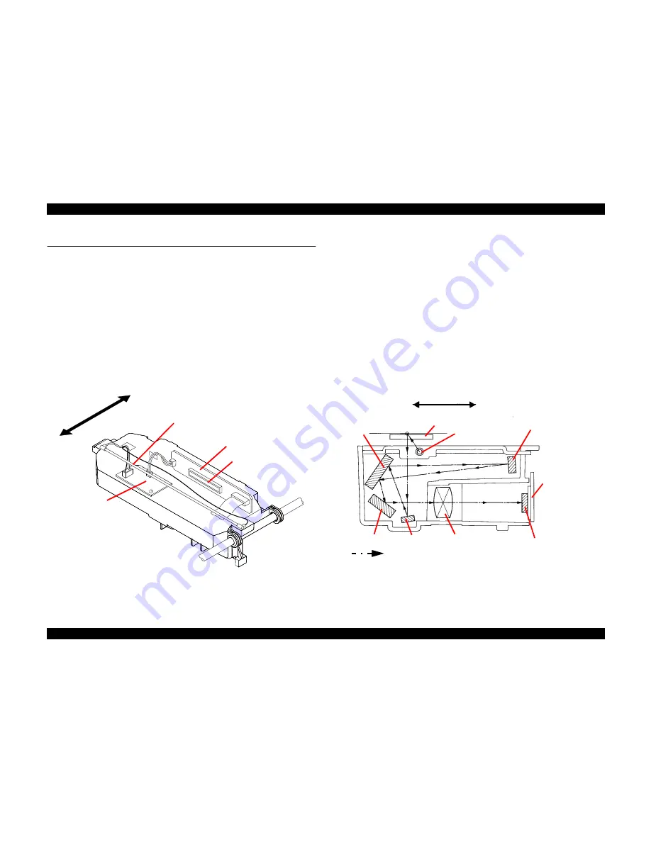
The carriage unit is composed of the following:
!
CCD sensor board (containing the CCD sensor)
!
Inverter board
!
Lamp (the light source)
!
Mirror and lens mechanism
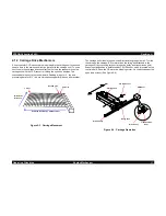
Figure 2-1. Carriage Unit Component
"
CCD Sensor Board
This board includes the Color CCD line sensor (independent R,G,B) and
the sensor’s control and driver circuits.
"
Inverter Board
This board generates voltage used to drive the lamp. The board pressures
up +24VDC and converts it from direct current to alternating current.
"
Lamp
A white cold fluorescent lamp is used as the light source.
"
Mirror and Lens Mechanism
Light emitted to the document reaches the CCD sensor via the mirror and
lens mechanism in the carriage unit, where the light’s optical axis is
corrected. Note other scanners separates R/G/B components by switching
the light source between R, G, and B. In this scanner, however, it is
performed by the CCD sensor itself.
Figure 2-2. Mirror, Lens Mechanism
Front
Rear
Lamp
CCD Sensor Board
Inverter Board
CCD Sensor
Lamp
Document
Mirror 3
CCD Sensor
Board
CCD Sensor
Lens
Mirror 1
Mirror 4
Mirror 2
Front
Rear
Scanned Image
Summary of Contents for Perfection 640U Series
Page 7: ...C H A P T E R 1 PRODUCTDESCRIPTION ...
Page 15: ...C H A P T E R 2 OPERATINGPRINCIPLES ...
Page 19: ...C H A P T E R 3 TROUBLESHOOTING ...
Page 23: ...C H A P T E R 4 ASSEMBLYANDDISASSEMBLY ...
Page 41: ...C H A P T E R 5 ADJUSTMENT ...
Page 43: ...C H A P T E R 6 MAINTENANCE ...
Page 45: ...C H A P T E R 7 APPENDIX ...
Page 53: ......


