EPSON Perfection 640U
Revision A
Assembly and Disassembly
Disassembly Procedures
32
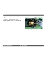
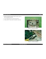
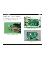
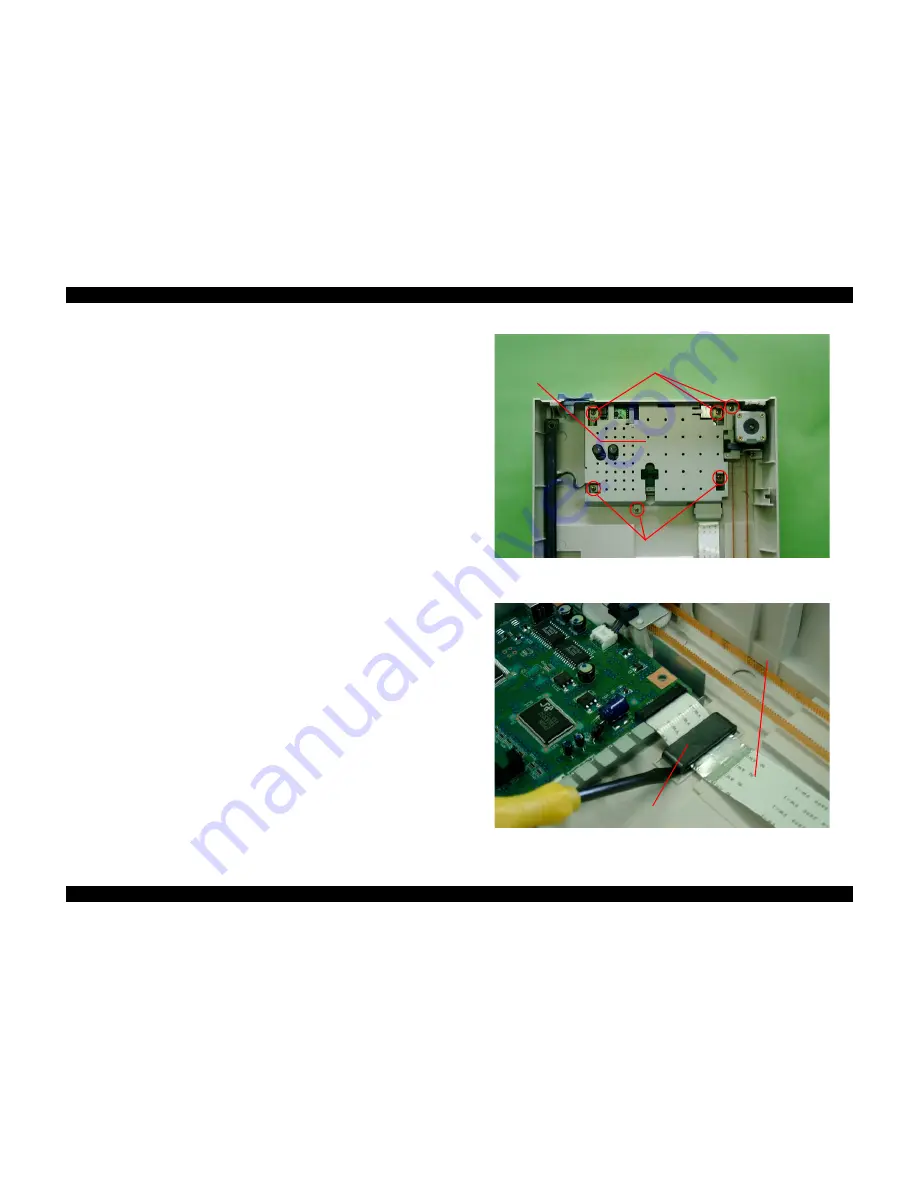
6. Remove the six screws (gold, CBP, M3x8), and then remove the
Main Circuit Board Shield Plate.
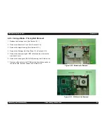
7. Use a standard screw driver to remove the Ferrite Core.
8. Disconnect the FFC Cable (white) from the Main Circuit Board.
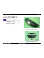
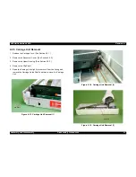
Figure 4-16. Shield Plate Removal
Figure 4-17. Ferrite Core Removal
6. CBS Screw (M3x8)
6. CBP Screws (M3x8)
6. Main Board Cover
FFC Cable
Ferrite Core
Summary of Contents for Perfection 640U Series
Page 7: ...C H A P T E R 1 PRODUCTDESCRIPTION ...
Page 15: ...C H A P T E R 2 OPERATINGPRINCIPLES ...
Page 19: ...C H A P T E R 3 TROUBLESHOOTING ...
Page 23: ...C H A P T E R 4 ASSEMBLYANDDISASSEMBLY ...
Page 41: ...C H A P T E R 5 ADJUSTMENT ...
Page 43: ...C H A P T E R 6 MAINTENANCE ...
Page 45: ...C H A P T E R 7 APPENDIX ...
Page 53: ......

