EPSON Perfection4180 Photo
Revision A
DISASSEMBLY/ASSEMBLY
Disassembly Procedure
37
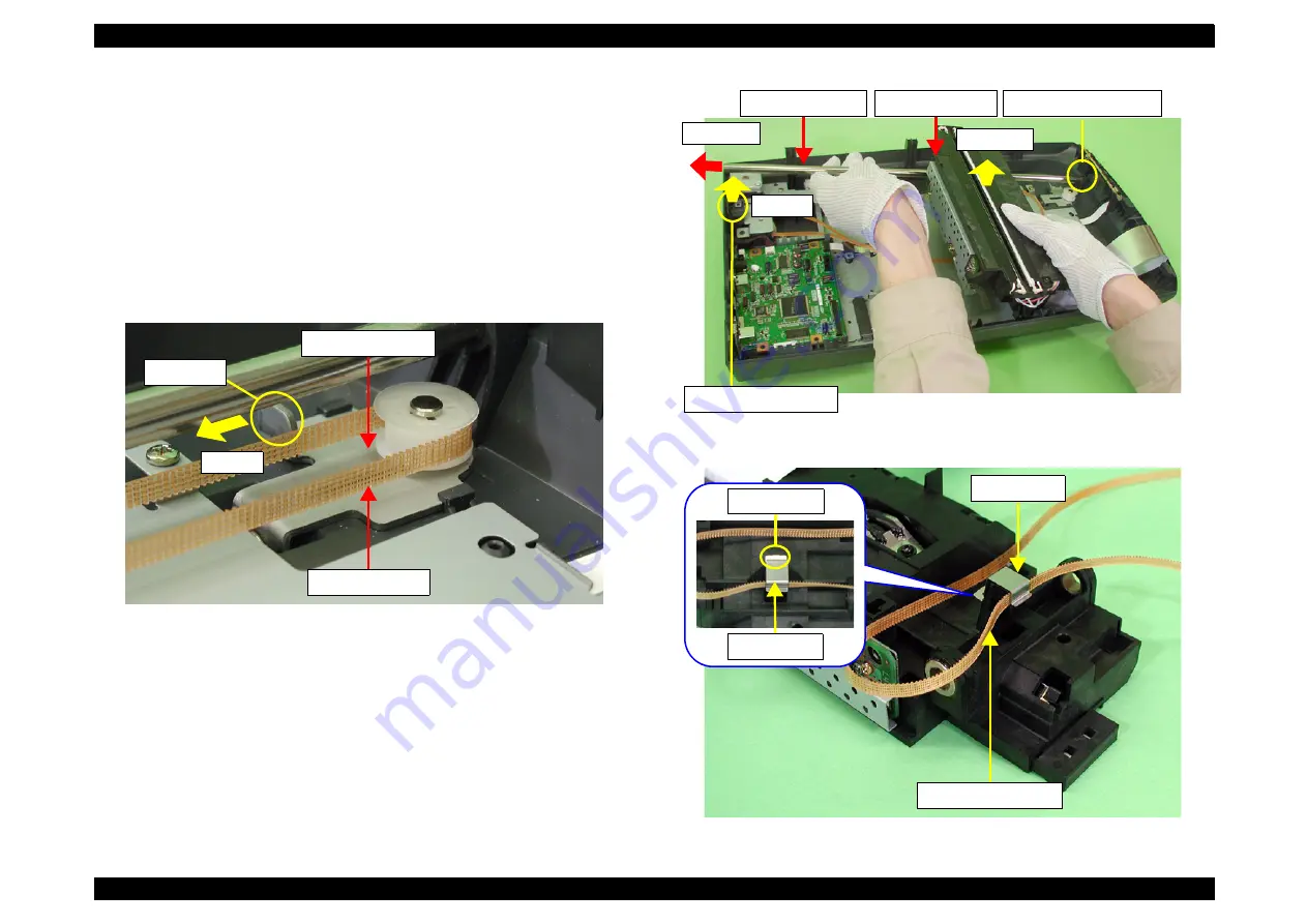
6. Pull the portion A of the Driven Pulley Set to the rear, and remove the CR Tension
Belt.
7. Remove the Carriage Shaft from the Bushing at the rear of the Housing Lower, and
while supporting the Carriage Unit by hand, remove the Carriage Shaft from the
Bushing at the front of the Housing Lower.
8. Slide the Carriage shaft to remove it from the Carriage Unit.
9. Turn the Carriage Unit over and pick the portion B (shown in the
) up to
release the catch, and then remove the Carriage Unit.
Figure 4-11. Removal of CR Tension Belt
Figure 4-12. Removal of Carriage Shaft
Figure 4-13. Removal of Carriage Unit
CR Tension Belt
Portion A
Driven Pulley Set
Step 8-2)
Step 8-1)
Rear side Bushing
Front side Bushing
Carriage Shaft
Carriage Unit
CR Tension Belt
Stop Plate
Stop Plate
Portion B
Summary of Contents for Perfection4180 Photo
Page 5: ...Revision Status Revision Date of Issue Description A July 30 2004 First release ...
Page 8: ...C H A P T E R 1 PRODUCTDESCRIPTION ...
Page 19: ...C H A P T E R 2 OPERATING PRINCIPLES ...
Page 23: ...C H A P T E R 3 TROUBLESHOOTING ...
Page 29: ...C H A P T E R 4 DISASSEMBLY ASSEMBLY ...
Page 52: ...C H A P T E R 5 ADJUSTMENT ...
Page 54: ...C H A P T E R 6 MAINTENANCE ...
Page 57: ...C H A P T E R 7 APPENDIX ...
Page 66: ...401 GT F600 PERFECTION 4180 PHOTO NO 1 Rev 01 B170 ACCE 001 10 20 30 40 402 400 ...


