EPSON PhotoPC 800
Revision A
Product Description
Indication and Switch Function
21
1.4 Indication and Switch Function
1.4.1 Indication and Switch
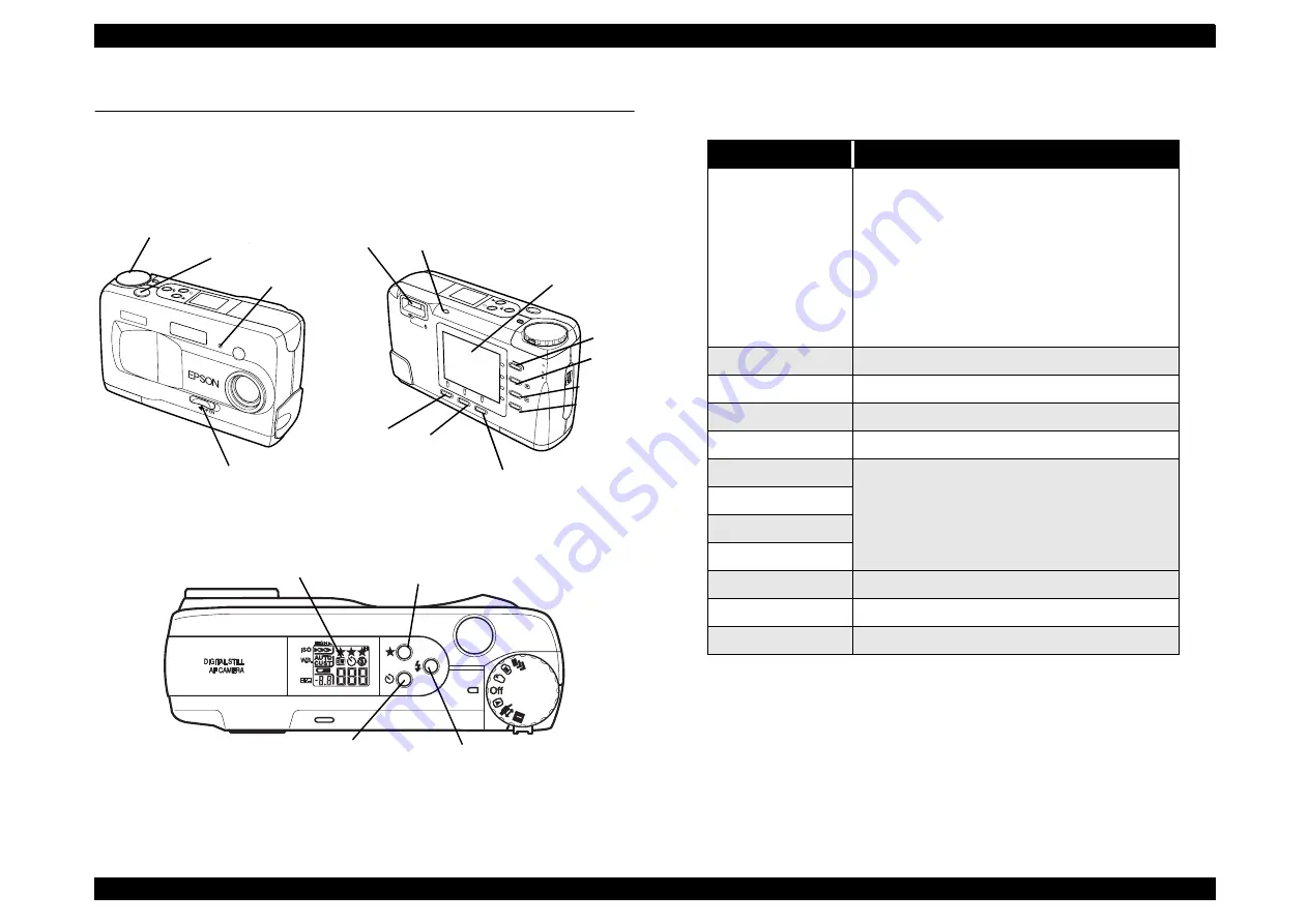
Figure below shows switches and indications.
Figure 1-2. Front and Rear
Figure 1-3. Top
1.4.1.1 Switches
Table 1-9. Switches
NOTE: VF: View Finder
Dial switch
Shutter
switch
Self-timer
lamp
Lens cover
switch
Status Lamp
LCD Monitor
VF&shooting
lamp
Button “A”
Button “B”
Button “C”
Button1
Button2
Button3
Button4
Display Panel
Resolution
switch
Flash switch
Self-timer
switch
Name
Functions
Dial switch
• Power and setting switch
• 7-mode rotary switch
*Special shooting mode (Continuous/interval
shooting)
*LCD shooting mode
*VF shooting mode
*OFF
*Playback mode
*Expansion function mode/PC connection mode
*SETUP mode
Shutter switch
2-step shutter/ Release button
Resolution switch
Image quality (
•
/
••
/
•••
/
•••
H
)
Flash switch
Flash setting (Auto/Forced/Off/Slow Synchro)
Self-timer switch
Self-timer setting (ON/OFF)
Button 1
MENU selection
Button 2 (+)
Button 3 (-)
Button 4
Button A
Menu selection/ON/OFF/Going to the next screen
Button B
Selection of expansion functions and connection
Button C
Various setting mode
Summary of Contents for PhotoPC 800
Page 1: ...EPSONPhotoPC800 Digital Still Camera SEDC99002 6 59 0 18 6 59 0 18 6 59 0 18 6 59 0 18 ...
Page 5: ...Revision Status Revision Issued Date Description A June 10 1999 First Release ...
Page 8: ... 3 7 5 4 PRODUCT DESCRIPTION ...
Page 32: ... 3 7 5 5 OPERATINGPRINCIPLE ...
Page 52: ... 3 7 5 6 TROUBLESHOOTING ...
Page 55: ... 3 7 5 7 DISASSEMBLYANDASSEMBLY ...
Page 74: ... 3 7 5 8 ADJUSTMENT ...
Page 90: ... 3 7 5 9 MAINTENANCE ...
Page 92: ... 3 7 5 APPENDIX ...
Page 94: ......
Page 96: ...ca1_pcb ...
Page 97: ...ca2_pcb ...
Page 98: ...sy1_pcb ...
Page 99: ...pw1_pcb ...
Page 101: ......
Page 102: ...NTSC ...
Page 103: ...PAL ...
Page 104: ......
Page 105: ......
Page 110: ......


