EPSON PhotoPC 800
Revision A
Operating Principle
Operating principles of the Circuit Boards
39
2.2.1.6 Lens Drive Clock
†
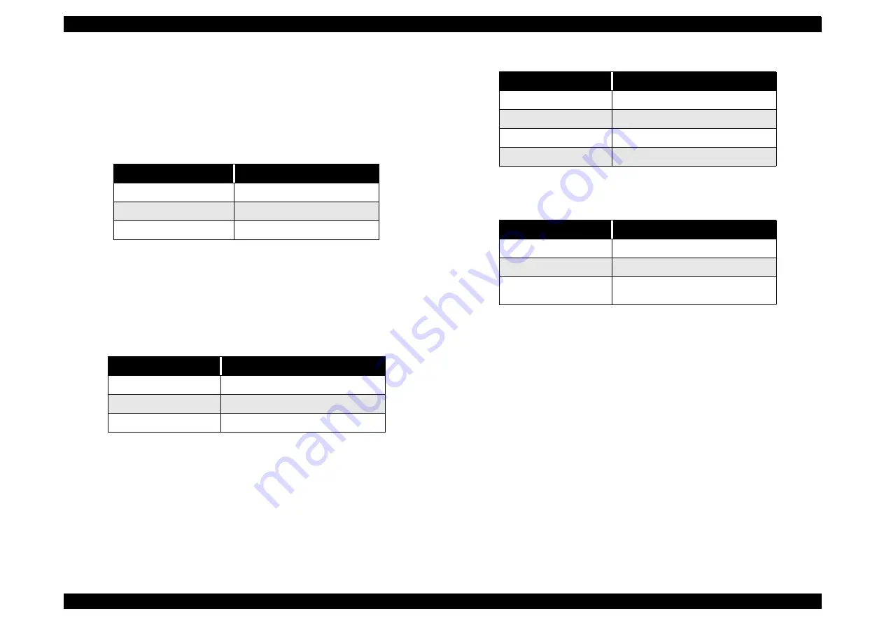
Shutter drive:
The two control signals (SIN1, SIN2) which are output from the ASIC
expansion port (IC106) are converted into drive pulses (SOUT1, SOUT2)
by the motor drive (IC951), and the shutter is opened and closed by regular
current drive.
Table 2-3. Shutter specification
†
Iris drive
The two control signals (IIN1, IIN2) which are output from the ASIC
expansion port (IC106) are converted into drive pulses (IOUT1, IOUT2) by
the motor drive (IC952), and the iris is opened and closed. Resistance
R9505, which is connected to IOUT2 of IC952 in series, is the current
control resistance for the minimum drive voltage of the iris motor.
Table 2-4. Iris specification
†
Focus drive
The four control signals (FIN1, FIN2, FIN3 and FIN4) with different phases
which are output from the ASIC are converted into drive pulses (FOUT1,
FOUT2, FOUT3 and FOUT4) by the motor driver (IC953), and are then
used to drive the stepping motor for focusing operation. Detection of the
standard focusing positions is carried out by means of the photointerruptor
(FOCUS PI) inside the lens block.
Table 2-5. Focus Motor specification
Table 2-6. Detection of Focus position
Item
Contents
Method
2-spring shutter
Current for motor driving
Maximum 200mA
Motor coil resistance
12
±
1
Ω
(at normal temperature)
Item
Contents
Focus step
2 steps (when F2.8 opens, F8)
Minimum drive voltage
1.4VDC
Motor coil resistance
12
±
1
Ω
(at normal temperature)
Item
Contents
Method
Stepping Motor
Driving voltage
3.4
±
1V
Driving frequency
480bps
Motor coil resistance
40
Ω ±
7% (at normal temperature)
Item
Contents
Method
Photo interrupter type
Driving voltage
5V
Judgement
• High: higher than 3.5V
• Low: less than 1.5V
Summary of Contents for PhotoPC 800
Page 1: ...EPSONPhotoPC800 Digital Still Camera SEDC99002 6 59 0 18 6 59 0 18 6 59 0 18 6 59 0 18 ...
Page 5: ...Revision Status Revision Issued Date Description A June 10 1999 First Release ...
Page 8: ... 3 7 5 4 PRODUCT DESCRIPTION ...
Page 32: ... 3 7 5 5 OPERATINGPRINCIPLE ...
Page 52: ... 3 7 5 6 TROUBLESHOOTING ...
Page 55: ... 3 7 5 7 DISASSEMBLYANDASSEMBLY ...
Page 74: ... 3 7 5 8 ADJUSTMENT ...
Page 90: ... 3 7 5 9 MAINTENANCE ...
Page 92: ... 3 7 5 APPENDIX ...
Page 94: ......
Page 96: ...ca1_pcb ...
Page 97: ...ca2_pcb ...
Page 98: ...sy1_pcb ...
Page 99: ...pw1_pcb ...
Page 101: ......
Page 102: ...NTSC ...
Page 103: ...PAL ...
Page 104: ......
Page 105: ......
Page 110: ......


