Maintenance 5. Switching Power Supply Module
RC420 Rev.9
121
5. Switching Power Supply Module
5.1 Layout and Functions
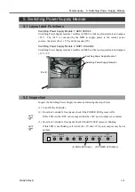
Switching Power Supply Module 1: AES100W-24
Switching Power Supply module 1 rectifies AC200V (or the local equivalent) and outputs
+24V. The +24V is converted by the DPB to supply power to the control power
sources: the motor driver (
-
5V) and the encoder (5V).
Switching Power Supply Module
2: NSP7-100-X2S2
Switching Power Supply module 2 rectifies AC200V (or the local equivalent) and outputs
+
12V, +5V.
(Front)
Switching Power Supply Module 1
Switching Power Supply Module 2
5.2 Inspection
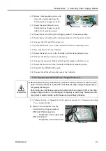
Inspect the Switching Power Supply modules by following the steps below:
(1) Turn ON the Controller.
(2) From the Controller’s front panel, check if the POWER LED (green) is ON.
If this LED is either OFF or dim, suspect that the
+
24V power output is not normal.
(3) From the Controller’s front panel, check if the RUN LED (green) is blinking.
If this LED is not blinking or it is dim, the +5V and +12V power outputs may be not
normal.
(2) POWER LED (Green)
ERROR POWER
1
2 D-ERROR RUN
E-STOP POWER SHUTDOWN
MOTOR
SAFE
STATUS
(3) RUN LED (Green)
)
NOTE
)
NOTE
Summary of Contents for RC420
Page 1: ...Rev 9 EM073C1492F ROBOT CONTROLLER RC420 ...
Page 2: ...ROBOT CONTROLLER RC420 Rev 9 ...
Page 12: ...Setup Operation ...
Page 20: ...Setup Operation 1 Safety 10 RC420 Rev 9 ...
Page 30: ...Setup Operation 2 3 Controller Part Names and Functions 20 RC420 Rev 9 ...
Page 50: ...Setup Operation 5 5 Circuit Diagrams EMERGENCY Connector 40 RC420 Rev 9 ...
Page 58: ...Setup Operation 6 3 Pin Assignments STANDARD I O Connector 48 RC420 Rev 9 ...
Page 114: ...Setup Operation 10 UPS Uninterruptible Power Supply 104 RC420 Rev 9 ...
Page 115: ...97 Maintenance This manual contains maintenance procedures for the RC420 Robot Controller ...
Page 116: ...Maintenance RC420 Rev 9 106 ...
Page 138: ...Maintenance 6 Motor Driver Module 128 RC420 Rev 9 ...
Page 170: ...Maintenance 12 Recovering the HDD 160 RC420 Rev 9 ...

