Maintenance 11. Verifying Robot System Operation
RC420 Rev.9
141
11. Verifying Robot System Operation
When either the Manipulator or Controller has been maintained or, when any parts were
replaced in those units, it must be checked according to the procedure in this section to ensure
that the new setting(s) operates normally.
(1) Completely connect all the necessary cables for the system.
WARNING
■
When verifying the robot system operation, prepare for failures with initial
settings or wiring. If the Manipulator operates unusually by the failures with
initial settings or wiring, press the Emergency Stop switch immediately to stop
the Manipulator.
Verify the robot system operation in the restricted (low speeds and low power)
status. Verifying the robot system operation at high speeds may damage the
robot system and/or cause serious safety problems as the Manipulator cannot
stop operating immediately in case of abnormal operation of the Manipulator.
CAUTION
■
The serial number of the Manipulator that should be connected is indicated on
the Connection Check Label on the Controller. Connect the Controller and the
Manipulator correctly. Improper connection between the Controller and the
Manipulator may cause not only improper function of the robot system but also
serious safety problems.
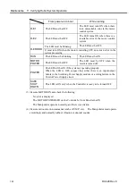
(2) Turn ON the Controller. Boot the Controller. During this process, watch and monitor
the LED status as described in the following list:
Controller – Front Panel LED
From power-on to boot
While running
7 segment
(STATUS)
When the main power is turned
ON, “8” lights up momentarily
and turns OFF.
The displayed data must change
from “0” in order to indicate
the system condition that is
checked at the beginning of the
Controller.
The LED is OFF under normal
conditions.
In case of system error, it must
display the status of the error by the
designated number. (For details,
refer to the
SPEL
+
Error Messages
in SPEL
+
Language Reference.)
ERROR
When the main power is turned
ON, the LED will turn ON
momentarily and will turn OFF.
The LED is OFF under normal
conditions. It must turn ON when
there is a system error.
E-STOP
When the main power is turned ON, this LED will turn ON
momentarily and will turn OFF unless there is an Emergency Stop input.
If there is an Emergency Stop input at this time, the LED will stay ON.
This LED turns ON when there is an Emergency Stop input to the
Controller’s OPTIONAL DEVICE connector and EMERGENCY
connector.
Summary of Contents for RC420
Page 1: ...Rev 9 EM073C1492F ROBOT CONTROLLER RC420 ...
Page 2: ...ROBOT CONTROLLER RC420 Rev 9 ...
Page 12: ...Setup Operation ...
Page 20: ...Setup Operation 1 Safety 10 RC420 Rev 9 ...
Page 30: ...Setup Operation 2 3 Controller Part Names and Functions 20 RC420 Rev 9 ...
Page 50: ...Setup Operation 5 5 Circuit Diagrams EMERGENCY Connector 40 RC420 Rev 9 ...
Page 58: ...Setup Operation 6 3 Pin Assignments STANDARD I O Connector 48 RC420 Rev 9 ...
Page 114: ...Setup Operation 10 UPS Uninterruptible Power Supply 104 RC420 Rev 9 ...
Page 115: ...97 Maintenance This manual contains maintenance procedures for the RC420 Robot Controller ...
Page 116: ...Maintenance RC420 Rev 9 106 ...
Page 138: ...Maintenance 6 Motor Driver Module 128 RC420 Rev 9 ...
Page 170: ...Maintenance 12 Recovering the HDD 160 RC420 Rev 9 ...


