Setup & Operation 2.3 Controller (Part Names and Functions)
RC420 Rev.9
15
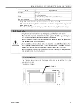
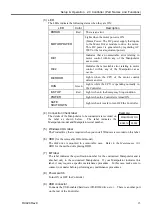
(3) LED
The LEDs indicate the following status when they are ON:
LED Color
Description
ERROR
Red
There is an error.
MOTOR POWER
Lights when the motor power is ON.
(Motor Power: The DC power supply that inputs
to the Motor Driver module to drive the motor.
This DC power is generated by regulating AC
200V or the local equivalent power.)
D-E1
Indicates that an unresettable error relating to
motor control with/in any of the Manipulator
axes occurs.
D-E2
Indicates that a resettable error relating to motor
control with/in any of the Manipulator axes
occurs.
D-ERROR
Lights when the CPU of the motor control
detects an error.
RUN
Green
Lights while the CPU is operating normally in
the Controller.
E-STOP
Red
Lights when in the Emergency Stop condition.
POWER
Lights when the Controller is turned ON.
SAFE
SHUTDOWN
Lights when it is safe to turn OFF the Controller.
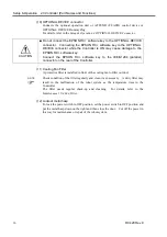
(4) Connection Check label
The details of the Manipulator to be connected are recorded on
the label as shown below. The label indicates the
Manipulator model and Manipulator serial number.
Example:
MANIPULATOR
00002
ES551S
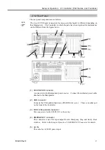
(5) Windows COA label
The Product Key that is required when you install Windows is recorded on this label.
(6) HDD (
for the removable HD unit model)
The disk drive is mounted in a removable case. Refer to the
Maintenance 10.3
HDD
for the method of replacing HDD.
(7) MT label
The label indicates the specification number for the customized Manipulator and is
attached only to the customized Manipulator. If your Manipulator indicates this
label, it may require a specific maintenance procedure. In this case, make sure to
contact your dealer before performing any maintenance procedures.
(8) Power switch
Turns ON or OFF the Controller.
(9) USB connector
Connects the USB-enabled hardware (CD-ROM drive, etc.). There is another port
on the rear of the Controller.
Summary of Contents for RC420
Page 1: ...Rev 9 EM073C1492F ROBOT CONTROLLER RC420 ...
Page 2: ...ROBOT CONTROLLER RC420 Rev 9 ...
Page 12: ...Setup Operation ...
Page 20: ...Setup Operation 1 Safety 10 RC420 Rev 9 ...
Page 30: ...Setup Operation 2 3 Controller Part Names and Functions 20 RC420 Rev 9 ...
Page 50: ...Setup Operation 5 5 Circuit Diagrams EMERGENCY Connector 40 RC420 Rev 9 ...
Page 58: ...Setup Operation 6 3 Pin Assignments STANDARD I O Connector 48 RC420 Rev 9 ...
Page 114: ...Setup Operation 10 UPS Uninterruptible Power Supply 104 RC420 Rev 9 ...
Page 115: ...97 Maintenance This manual contains maintenance procedures for the RC420 Robot Controller ...
Page 116: ...Maintenance RC420 Rev 9 106 ...
Page 138: ...Maintenance 6 Motor Driver Module 128 RC420 Rev 9 ...
Page 170: ...Maintenance 12 Recovering the HDD 160 RC420 Rev 9 ...

