Setup & Operation 3.4 Noise Countermeasures (Installation)
28
RC420 Rev.9
3.4 Noise Countermeasures
To minimize electrical noise conditions, the following items must be observed in the
system’s cable wiring:
- The earth wire of the power supply should be grounded. (Ground resistance: 100
Ω
or
less)It is important to ground the frame of Controller not only for prevention from
electric shock, but also for reducing the influence of electric noise around the
Controller. Therefore, be sure to connect the earth wire (yellow/green) of the
Controller’s power cable to the ground terminal of the factory power supply. For
details about the plug and AC power cable, refer to the
Setup & Operation “3.2.2
Power Plug
.
- Do not tap power from a power line that connects to any equipment which may cause
noise.
- When you tap power for the Controller and the single-phase AC motor from the same
power line, change the phase of one or the other. Ensure that they will not be the
same phase.
- Use a twisted pair motor power line.
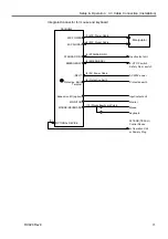
- Do not run AC power lines and DC power lines in
the same wiring duct, and separate them by at least
200 mm. For example, separate the AC motor
power line and the Controller power line by at least
200 mm from the sensor or valve I/O lines; and do
not bundle both sets of wiring with the same cable
tie. If more than one duct/cable must cross each
other, they should cross perpendicularly. The
preferable example is shown in the right figure.
AC Line duct
DC line duct
200 mm or more
- For I/O lines, wire as short as possible and use a shielded cable and clamp the shield to
the attached connector interior.
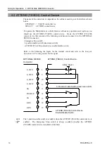
- Use a shielded cable for the EMERGENCY connector and clamp the shield to the
interior of the connector.
- Make sure that the induction elements used to connect to the Controller’s I/O (such as
relays and solenoid valves) have surge suppressors. If an induction element without
surge suppressor has be used, make sure to connect a rectifying diode right in front of
the induction element. In selecting a rectifying diode, make sure that it can handle
the voltage and current incurred by the induction load.
- To start and change revolutions of the conveyer’s (or the like’s) AC motor (ex: an
induction motor or three-phase induction motor) regularly or abruptly, make sure to
install a spark suppressor between the wires. The spark suppressor is more effective
when placed closer to the motor.
- As they are easily influenced by static electricity or the noise from power source, keep
the mouse and keyboard away from peripheral noise sources.
It is sometimes effective in suppressing such noise to wind the keyboard or mouse cables
around a ferrite core several times.
)
NOTE
Summary of Contents for RC420
Page 1: ...Rev 9 EM073C1492F ROBOT CONTROLLER RC420 ...
Page 2: ...ROBOT CONTROLLER RC420 Rev 9 ...
Page 12: ...Setup Operation ...
Page 20: ...Setup Operation 1 Safety 10 RC420 Rev 9 ...
Page 30: ...Setup Operation 2 3 Controller Part Names and Functions 20 RC420 Rev 9 ...
Page 50: ...Setup Operation 5 5 Circuit Diagrams EMERGENCY Connector 40 RC420 Rev 9 ...
Page 58: ...Setup Operation 6 3 Pin Assignments STANDARD I O Connector 48 RC420 Rev 9 ...
Page 114: ...Setup Operation 10 UPS Uninterruptible Power Supply 104 RC420 Rev 9 ...
Page 115: ...97 Maintenance This manual contains maintenance procedures for the RC420 Robot Controller ...
Page 116: ...Maintenance RC420 Rev 9 106 ...
Page 138: ...Maintenance 6 Motor Driver Module 128 RC420 Rev 9 ...
Page 170: ...Maintenance 12 Recovering the HDD 160 RC420 Rev 9 ...


