Setup & Operation 4. OPTIONAL DEVICE Connector
32
RC420 Rev.9
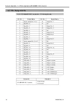
4.4 Pin Assignments
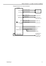
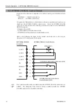
In case you wish to connect the ATTEND (TEACH) control device enable/disable switch
to the OPTIONAL DEVICE connector, refer to the following pin assignments.
Pin number
Signal name
Pin number
Signal name
1 FG
14 ENABLE
2
Not to be used
15
SG
3
Not to be used
16
Not to be used
4
Not to be used
17
Not to be used
5
Not to be used
18
KEY1
6 E_SW11
19 KEY2
7
SG
20
Not to be used
8
Not to be used
21
Not to be used
9
E_SW21
22
Not to be used
10
E_SW12
23
Not to be used
11
E_SW22
24
Not to be used
12
Not to be used
25 +12V
13 SG
Each mode is dictated by the signals at KEY1 and KEY2 as follows:
Operation Condition
KEY1 KEY2
Enabled
Connect to SG (13 pin)
Open
The ATTEND (TEACH)
control device
Disabled
Open
Connect to SG (13 pin)
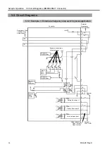
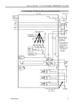
If you are connecting an Emergency Stop switch, connect it to the EMERGENCY
connector on the rear of the Controller.
Summary of Contents for RC420
Page 1: ...Rev 9 EM073C1492F ROBOT CONTROLLER RC420 ...
Page 2: ...ROBOT CONTROLLER RC420 Rev 9 ...
Page 12: ...Setup Operation ...
Page 20: ...Setup Operation 1 Safety 10 RC420 Rev 9 ...
Page 30: ...Setup Operation 2 3 Controller Part Names and Functions 20 RC420 Rev 9 ...
Page 50: ...Setup Operation 5 5 Circuit Diagrams EMERGENCY Connector 40 RC420 Rev 9 ...
Page 58: ...Setup Operation 6 3 Pin Assignments STANDARD I O Connector 48 RC420 Rev 9 ...
Page 114: ...Setup Operation 10 UPS Uninterruptible Power Supply 104 RC420 Rev 9 ...
Page 115: ...97 Maintenance This manual contains maintenance procedures for the RC420 Robot Controller ...
Page 116: ...Maintenance RC420 Rev 9 106 ...
Page 138: ...Maintenance 6 Motor Driver Module 128 RC420 Rev 9 ...
Page 170: ...Maintenance 12 Recovering the HDD 160 RC420 Rev 9 ...


