2. Installation
234
RC700 / RC90 Option Fieldbus I/O Rev.14
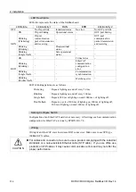
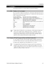
LED Description
LED state represents the states of the fieldbus board.
LED state
Link/Activity 1
RUN
ERR
Link/Activity 2
OFF
No IN port link
Initialized status
No error
No OUT port link
GRN
ON
IN port linking
Operational status
−
OUT port linking
Blinking
(Flickering)
IN port
communication
packet transmission
and receiving
−
−
OUT port
communication
packet transmission
and receiving
Blinking
(Blinking)
−
Preoperational
status
−
−
Blinking
(Single flash)
−
Safe operational
status
−
−
RED
ON
−
−
Critical error
−
Blinking
(Blinking)
−
−
EtherCAT
communication
configuration
error
−
Blinking
(Single flash)
−
−
Communication
synchronization
−
Blinking
(Double flash)
−
−
Watchdog error
−
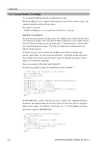
LED’s blinking patterns are as follows:
Flickering
: Repeats lighting on and off every 50 ms.
Blinking
: Repeats lighting on and off every 200 ms.
Single flash
: Repeats 200 ms of lighting on and 1000 ms c of lighting off.
Double flash
: Repeats a cycle of 200 ms of lighting on, 200 ms of lighting off,
200 ms of lighting on and 1000 ms of lighting off.
Setting Configure Switch
Configuration of an EtherCAT board is not necessary. All settings such as communication
configuration for EtherCAT are done by EPSON RC+ 7.0.
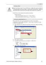
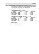
Wiring
Wiring of an EtherCAT slave board uses RJ45 connectors. Make sure to use STP-type
100BASE-TX cables.
CAUTION
For cables and connectors, be sure to use a product complying with the industrial
standards or a noise-resistant Ethernet cable (STP cable). If you use office use
products or UTP cables, it may cause communication errors and may not offer the
proper performance.
Summary of Contents for RC700
Page 1: ...Robot Controller RC700 RC90 Option Fieldbus I O Rev 14 EM198C4088F ...
Page 2: ...Robot Controller RC700 RC90 Option Fieldbus I O Rev 14 ...
Page 8: ...vi RC700 RC90 Option Fieldbus I O Rev 14 ...
Page 12: ...Table of Contents x RC700 RC90 Option Fieldbus I O Rev 14 ...
Page 340: ...5 Maintenance Parts List 328 RC700 RC90 Option Fieldbus I O Rev 14 ...


