1. Safety
14
Safety and Installation (RC90-B / EPSON RC+ 7.0) Rev.4
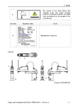
LS3-B, LS6-B
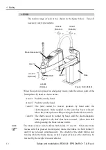
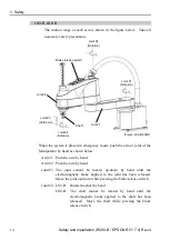
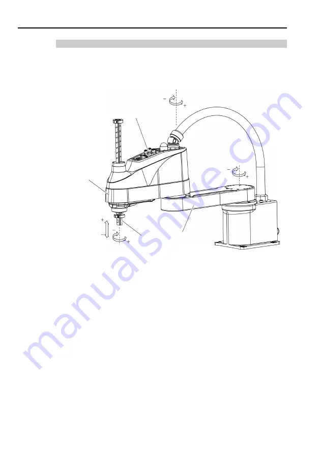
The motion range of each arm is shown in the figure below. Take all
necessary safety precautions.
Brake release switch
Joint #1
(Rotation)
Joint #2
(Rotation)
Joint #4
(Rotation)
Joint #3
(Up/Down)
Arm #1
Arm #2
Shaft
(Figure: LS6-B602S)
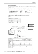
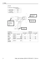
When the system is placed in emergency mode, push the arm or joint of the
Manipulator by hand as shown below:
Arm #1 Push the arm by hand.
Arm #2 Push the arm by hand.
Joint #3 The joint cannot be moved up/down by hand until the
electromagnetic brake applied to the joint has been released.
Move the joint up/down while pressing the brake release switch.
Joint #4 LS3-B Rotate the shaft by hand.
LS6-B The shaft cannot be rotated by hand until the
electromagnetic brake applied to the shaft has been
released. Move the shaft while pressing the brake
release switch.
Summary of Contents for RC90-B
Page 2: ...Robot System Safety and Installation RC90 B EPSON RC 7 0 Rev 4 ...
Page 16: ...Table of Contents xiv Safety and Installation RC90 B EPSON RC 7 0 Rev 4 ...
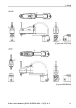
Page 46: ...1 Safety 30 Safety and Installation RC90 B EPSON RC 7 0 Rev 4 LS3 B Figure LS3 B401S ...
Page 126: ...7 Directives and Norms 110 Safety and Installation RC90 B EPSON RC 7 0 Rev 4 ...


