Maintenance 3. Controller Structure
RC90 (EPSON RC+ 7.0) Rev.8
85
3. Controller Structure
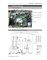
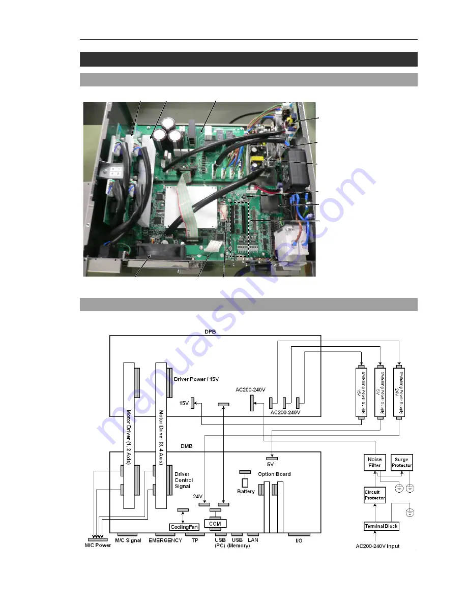
3.1 Location of Parts
MDB2
DPB
24V
Switching Power Supply Module
MDB1
Fan
DMB Sub Board
DMB
5V
Switching Power Supply Module
15V
Switching Power Supply Module
Option Slots
CF
Battery
3.2 Diagram of Cable Connections
For the electrical connections of the Controller, refer to the following diagram.
Summary of Contents for RC90
Page 1: ...Rev 8 EM158C3031F ROBOT CONTROLLER RC90 EPSON RC 7 0 ...
Page 2: ...ii ROBOT CONTROLLER RC90 EPSON RC 7 0 Rev 8 ...
Page 10: ...viii RC90 EPSON RC 7 0 Rev 8 ...
Page 17: ...Safety This section contains information for safety of the Robot System ...
Page 18: ......
Page 24: ......
Page 28: ...Setup Operation 1 Specifications 12 RC90 EPSON RC 7 0 Rev 8 1 3 Outer Dimensions Unit mm ...
Page 95: ...Maintenance This section contains maintenance procedures for the Robot Controller ...
Page 96: ......

