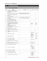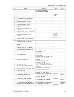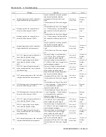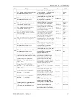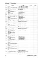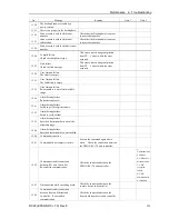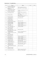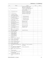
Maintenance 7. Maintenance Parts Replacement Procedures
RC90 (EPSON RC+ 7.0) Rev.8
111
7.8 Option Board
Option Board
Addition
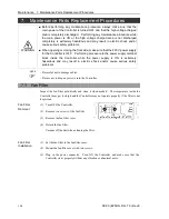
(1) Turn OFF the Controller.
(2) Unplug the power connector.
(3) Remove the Top Panel. (Mounting screws
×
10)
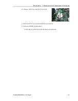
(4) Remove the clamp of the power supply cable.
(5) Remove the screws of the Option Slot Panel
(
×
4).
When installing one Option Board:
Slide the panel as shown in the picture and
install the board with screws (
×
2).
When installing two Option Boards:
The Option Slop Panel is not necessary.
(6) Install the Option Board as shown in the picture.
(7) Mount the attachment L-shaped plate with a
screw from the front side.
At this point, one screw for the Option Slot
Panel is left unused.
(8) Secure the L-shaped plate and Option Board
with the attachment screw.
(9) Mount the clamp of the power cable.
Summary of Contents for RC90
Page 1: ...Rev 8 EM158C3031F ROBOT CONTROLLER RC90 EPSON RC 7 0 ...
Page 2: ...ii ROBOT CONTROLLER RC90 EPSON RC 7 0 Rev 8 ...
Page 10: ...viii RC90 EPSON RC 7 0 Rev 8 ...
Page 17: ...Safety This section contains information for safety of the Robot System ...
Page 18: ......
Page 24: ......
Page 28: ...Setup Operation 1 Specifications 12 RC90 EPSON RC 7 0 Rev 8 1 3 Outer Dimensions Unit mm ...
Page 95: ...Maintenance This section contains maintenance procedures for the Robot Controller ...
Page 96: ......

