background image

Maintenance  9. Troubleshooting 


RC90 (EPSON RC+ 7.0) Rev.8


121 

No. 

Message 

Remedy 

Note 1 

Note 2 

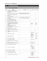
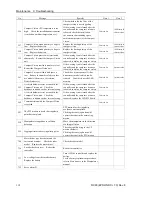
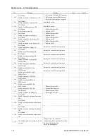
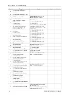
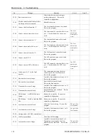
1103 

File is not found. 

Check whether the file exists. 


1104 

Project file was not found. 

Rebuild the project. 


1105 

Object file was not found. 

Rebuild the project. 


1106 

Point files were not found. 

Rebuild the project. 


1107 

The program is using a feature that is 
not supported by the current controller 
firmware version. 

Check the compiler version in the 
EPSON RC+ 
7.0-[Project]-[Properties]-[Compiler]. 


1108 

One or more source files are updated. 
Please build the project. 

Rebuild the project. 


1109 

Not enough storage capacity. 

Increase free space of the USB memory. 


1110 

File is not found. 


1111 

Conveyor file was not found. 


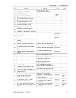
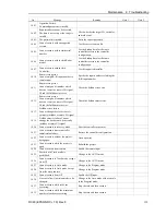
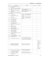
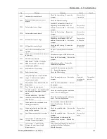
1120 

File failure. 
Setting file is corrupt. 

Restore the controller configuration. 


1121 

File failure. 
Project file is corrupt. 

Rebuild the project. 


1122 

File failure. 
Point file is corrupt. 

Rebuild the project. 


1123 

File failure.   
I/O label file is corrupt. 

Rebuild the project. 


1124 

File failure.   
User error file is corrupt. 

Rebuild the project. 


1126 

File failure. 
Software option information is 
corrupt. 

1.


Reboot the controller.   

2.


Reinstall the firmware.   

3.


Reconfigure the option. 


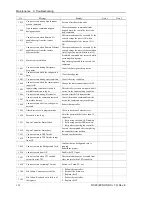
1127 

File failure. 
Vision file is corrupt. 

Rebuild the project. 


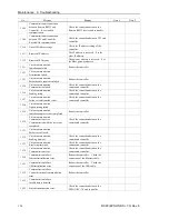
1128 

File failure. 
Backup information file is corrupt. 

The specified backup information cannot 
be restored. 
Acquire the backup information again, 
and then restore the file. 


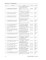
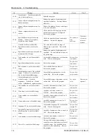
1130 

Error message failure. 
No item is found in the error history. 

No error history exists. 
Reboot the controller. 


1131 

Cannot access the USB memory. 

Insert the USB memory properly. When 
this error still occurs after the USB 
memory is inserted properly, the 
memory may be unrecognizable to 
controller.    Insert another memory to 
check the operation. 


1132 

File failure. 
Failed to copy the file. 


1133 

File failure. 
Failed to delete the file. 


1134 

File failure. 
GUI Builder file is corrupt. 

Rebuild the project. 


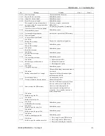
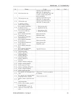
1140 

File failure. 
Failed to open the object file. 

Rebuild the project. 


1141 

File failure. 
Failed to open the project file. 

Rebuild the project. 


1142 

File failure. 
Failed to read the project file. 

Rebuild the project. 


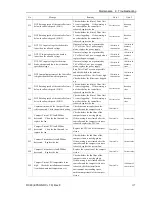
1143 

File failure. 
Failed to open the condition save file. 

1.


Retry using the same USB memory. 

2.


Retry using another USB memory. 

3.


Retry after rebooting the controller. 


Summary of Contents for RC90

Page 1: ...Rev 8 EM158C3031F ROBOT CONTROLLER RC90 EPSON RC 7 0 ...

Page 2: ...ii ROBOT CONTROLLER RC90 EPSON RC 7 0 Rev 8 ...

Page 3: ...RC90 EPSON RC 7 0 Rev 8 i ROBOT CONTROLLER RC90 EPSON RC 7 0 Rev 8 Copyright 2013 2015 SEIKO EPSON CORPORATION All rights reserved ...

Page 4: ...ce for warranty period information However customers will be charged for repairs in the following cases even if they occur during the warranty period 1 Damage or malfunction caused by improper use which is not described in the manual or careless use 2 Malfunctions caused by customers unauthorized disassembly 3 Damage due to improper adjustments or unauthorized repair attempts 4 Damage caused by na...

Page 5: ...ems In some cases Windows refers generically to Windows XP Windows Vista Windows 7 and Windows 8 NOTICE No part of this manual may be copied or reproduced without authorization The contents of this manual are subject to change without notice Please notify us if you should find any errors in this manual or if you have any comments regarding its contents INQUIRIES Contact the following service cente...

Page 6: ...AX 1 562 290 5999 E MAIL info robots epson com Europe Epson Deutschland GmbH Factory Automation Division Otto Hahn Str 4 D 40670 Meerbusch Germany TEL 49 0 2159 538 1391 FAX 49 0 2159 538 3170 E MAIL robot infos epson de China Epson China Co Ltd Factory Automation Division 7F Jinbao Building No 89 Jinbao Street Dongcheng District Beijing China 100005 TEL 86 0 10 8522 1199 FAX 86 0 10 8522 1120 Tai...

Page 7: ... 1 HarbourFront Place 03 02 HarbourFront Tower One Singapore 098633 TEL 65 0 6586 5696 FAX 65 0 6271 3182 India Epson India Pvt Ltd Sales Marketing Factory Automation 12th Floor The Millenia Tower A No 1 Murphy Road Ulsoor Bangalore India 560008 TEL 91 80 3051 5000 FAX 91 80 3051 5005 Japan Epson Sales Japan Corporation Factory Automation Systems Department Nishi Shinjuku Mitsui Bldg 6 24 1 Nishis...

Page 8: ...C90 and the development PC are connected without installing the EPSON RC 7 0 to the development PC Add New Hardware Wizard appears If this wizard appears click the Cancel button Concerning the security support for the network connection The network connecting function Ethernet on our products assumes the use in the local network such as the factory LAN network Do not connect to the external networ...

Page 9: ...SON RC 7 0 RC90 controller firmware Ver 7 0 2 0 EPSON RC 7 0 Before Ver 7 0 1 Ver 7 0 2 or later OK OK Compatible All functions of the EPSON RC 7 0 and the Controller are available Compatible Connection is OK We recommend using EPSON RC 7 0 Ver 7 0 2 or later Manual PDF for this robot system is available from EPSON RC 7 0 Ver 7 0 2 This option is not available for Robot Controller RC90 EPSON RC 5 ...

Page 10: ...viii RC90 EPSON RC 7 0 Rev 8 ...

Page 11: ...s and Functions 13 2 1 Part Names 13 2 2 Functions 13 2 3 LED 15 2 4 Safety Features 16 3 Installation 18 3 1 Unpacking 18 3 2 Environmental Requirements 18 3 2 1 Environment 18 3 2 2 Installation 19 3 3 Power Supply 20 3 3 1 Specifications 20 3 3 2 AC Power Cable 21 3 3 3 M C Power Cable 22 3 4 Cable Connection 23 3 4 1 Typical Cable Connection 23 3 4 2 Connecting Manipulator to Controller 25 3 5...

Page 12: ...4 Disconnection of Development PC and Controller 33 6 Memory Port 34 6 1 What is Controller Status Storage Function 34 6 2 Before Using Controller Status Storage Function 34 6 2 1 Precautions 34 6 2 2 Adoptable USB Memory 34 6 3 Controller Status Storage Function 35 6 3 1 Controller Status Storage with Trigger Button 35 6 3 2 Load Data with EPSON RC 7 0 35 6 3 3 Transfer with E mail 37 6 4 Details...

Page 13: ... Stop 46 9 3 Pin Assignments 47 9 4 Circuit Diagrams 48 9 4 1 Example 1 External emergency stop switch typical application48 9 4 2 Example 2 External safety relay typical application 49 10 Standard RS 232C Port 50 10 1 About the RS 232C Port 50 10 2 Confirmation with EPSON RC 7 0 50 10 3 RS 232C Software Communication Setup RS 232C 51 10 4 Communication Cable RS 232C 51 11 I O Connector 52 11 1 In...

Page 14: ... 13 1 What are Option Slots 68 13 2 Expansion I O Board 68 13 2 1 About Expansion I O Board 68 13 2 2 Board Configuration Expansion I O 68 13 2 3 Confirmation with EPSON RC 7 0 69 13 2 4 Input Circuit 69 13 2 5 Output Circuit 71 13 2 6 Pin Assignments 74 13 3 Fieldbus I O Board 75 13 4 RS 232C Board 76 13 4 1 About the RS 232C Board 76 13 4 2 Board Setup 76 13 4 3 Confirmation with EPSON RC 7 0 RS...

Page 15: ...cedure 90 5 3 Controller Recovery 93 5 4 Firmware Initialization Procedure 94 6 Alarm 96 6 1 Alarm Configuration 96 6 1 1 Robot Battery and Grease Up 96 6 1 2 Controller Battery 97 6 2 How to View the Alarm Information 97 6 3 How to Edit the Alarm Information 98 6 4 Alarm Notifying Method 98 6 5 How to Cancel the Alarm 99 6 5 1 Alarm Cancellation Dialog 99 6 5 2 Remote Input 99 7 Maintenance Parts...

Page 16: ...13 9 Troubleshooting 114 9 1 Error Code Table 114 9 2 Cannot Connect the Development PC and the Controller using the USB cable 206 9 2 1 Confirmation Using Windows Device Manager 207 9 2 2 When recognized under Other devices in Windows Device Manager 209 10 Maintenance Parts List 210 ...

Page 17: ...Safety This section contains information for safety of the Robot System ...

Page 18: ......

Page 19: ... considerations are indicated throughout the manual by the following symbols Be sure to read the descriptions shown with each symbol WARNING This symbol indicates that a danger of possible serious injury or death exists if the associated instructions are not followed properly WARNING This symbol indicates that a danger of possible harm to people caused by electric shock exists if the associated in...

Page 20: ... respective manuals This product has been designed and manufactured strictly for use in a normal indoor environment Using the product in an environment that exceeds the specified environmental conditions may not only shorten the life cycle of the product but may also cause serious safety problems The robot system must be used within the installation requirements described in the manuals Using the ...

Page 21: ... is done by qualified personnel When connecting the plug be sure to connect the earth wire of the AC power cable colored green yellow on the Controller to the earth terminal of the factory power supply The equipment must be grounded properly at all times to avoid the risk of electric shock Always use a power plug and receptacle Never connect the Controller directly to the factory power supply Fiel...

Page 22: ...e the switch is disabled Example Tape is put around the switch to hold it closed Operating the robot system when the switch is not functioning properly is extremely hazardous and may cause serious safety problems as the Safety Door input cannot fulfill its intended function WARNING Do not open the cover s of the Controller except while maintaining it Opening the cover s of the Controller is extrem...

Page 23: ...Setup Operation This section contains information for setup and operation of the Robot Controller ...

Page 24: ......

Page 25: ...indows 7 Professional Windows 8 1 Pro EPSON RC 7 0 Ver 7 1 0 or later Operation panel Motion Controller RC90 Expansion I O Board Fieldbus PROFIBUS DP DeviceNet CC Link EtherNet IP PROFINET EtherCAT RS 232C Board Windows 1 PC EPSON RC 7 0 Software Option USB 2 0 or Ethernet TP2 Option Standard I O Remote I O Ethernet RS 232C Requires preparation by users LS series PLC Sequencer Option Standard PG B...

Page 26: ... Point To Point control CP Continuous Path control Memory capacity Maximum Object Size 4 MB Point data area 1000 points per file Backup variable area Max 100 KB Includes the memory area for the management table Approx 1000 variables Depends on the size of array variables Teaching method Remote Direct MDI Manual Data Input External input output signals standard Standard I O Input 24 Output 16 Inclu...

Page 27: ...elding detection Over voltage detection AC power supply voltage reduction detection Temperature error detection Fan error detection Power Source 200 VAC to 40 VAC Single phase 50 60 Hz Maximum Power Consumption 2 5 kVA Depending on the Manipulator model Insulation Resistance 100 MΩ or more Rated Ambient Temperature 5 to 40 deg C Rated Relative Humidity 20 to 80 with no condensation Weight 1 7 5 kg...

Page 28: ...Setup Operation 1 Specifications 12 RC90 EPSON RC 7 0 Rev 8 1 3 Outer Dimensions Unit mm ...

Page 29: ...nd clean it when necessary A dirty filter may result in malfunction of the robot system due to temperature rise of the Controller 5 Signature label The serial number of the Controller and other information are shown 6 MT label The label indicates the specification number of the customized manipulator or controller If this label is attached to your manipulator or controller it may require a specifi...

Page 30: ...l OP1 13 Development PC connection port This port connects the Controller and the Development PC using a USB cable Do not connect other devices except the Development PC For details refer to Setup Operation 5 Development PC Connection Port 14 Memory port This port connects the common USB memory for Controller status storage function Do not connect other USB devices except the USB memory For detail...

Page 31: ...ror Emergency Stop TEACH mode Auto mode Program mode From turning ON the Controller to completing startup Three LEDs TEACH AUTO PROGRAM blink After Controller Startup Controller status LED display Execute Controller status storage function to the USB memory TEACH AUTO PROGRAM blink Complete Controller status storage to USB memory TEACH AUTO PROGRAM turn ON for 2 seconds ERROR turns OFF even if an ...

Page 32: ...sed and the latched condition is released In order to execute the Manipulator operation while the safety door is open you must change the mode selector key switch on the Teach Pendant to the Teach mode Manipulator operation is available only when the enable switch is on In this case the Manipulator is operated in low power status Low Power Mode The motor power is reduced in this mode Executing a p...

Page 33: ...side the Controller are also designed to constantly check each other for any discrepancies If a discrepancy is detected the dynamic brake circuit is activated Memory Check sum Error Detection The dynamic brake circuit is activated when a memory check sum error is detected Overheat Detection at the Motor Driver Module The dynamic brake circuit is activated when the temperature of the power device i...

Page 34: ...e to install it in a proper enclosure with adequate ventilation and cooling Install Controller in a location that allows easy connection disconnection of cables Item Condition Ambient temperature 5 to 40 deg C with minimal variation Ambient relative humidity 20 to 80 with no condensation First transient burst noise 2 kV or less Power supply wire 1 kV or les Signal wire Electrostatic noise 4 kV or ...

Page 35: ...ocess screw holes as follows 133 35 mm 463 mm Ensure the draft around the in out and prevent the other equipments walls and install the Controller by keeping the distance as follows for maintenance 50 mm 50 mm 100 mm Excluding the installation side such as base table Air flow of the Controller Fan 100 mm 200 mm Hot air with higher temperature than the ambient temperature about 10 deg C comes out f...

Page 36: ...r Manipulator rated consumption Peak Current When power is turned ON approximately 70 A 2 msec When motor is ON approximately 50 A 2 msec Leakage Current Max 10 mA Ground Resistance 100 Ω or less Install an earth leakage circuit breaker or a circuit breaker in the AC power cable line at 15 A or less rated electric current Both should be a two pole disconnect type If you install an earth leakage ci...

Page 37: ... be grounded properly at all times to avoid the risk of electric shock Always use a power plug and receptacle for power connecting cable Never connect the Controller directly to the factory power supply Field wiring The AC plug is the optional parts Attach a proper plug to the cable that is suitable for the factory power supply Connection Specification of Cable Wire Purpose Color AC power wire 2 c...

Page 38: ...C 7 0 Rev 8 3 3 3 M C Power Cable 1 Mount the M C Power Cable as shown in the picture and form the cables 2 Set the M C Power Cable in the clamp for the M C Power Cable 3 Mount the cover for the M C Power Connector 4 Secure the cover with the screw ...

Page 39: ...serial number of the Manipulator that should be connected is indicated on the Connection Check Label on the Controller Connect the Controller and the Manipulator correctly Improper connection between the Controller and the Manipulator may cause not only improper function of the robot system but also safety problems Before connecting the connector make sure that the pins are not bent Connecting wit...

Page 40: ...etup Operation 9 EMERGENCY 5 PC for development Connect the PC for development For details refer to the Setup Operation 5 Development PC Port 6 USB memory Connect the USB memory For details refer to the Setup Operation 6 Memory Port 7 LAN EtherNet Communication Connect the EtherNet cable For details refer to the Setup Operation 7 LAN Ethernet Communication Port 8 I O connector This connector is us...

Page 41: ...uld be connected is indicated on the Connection Check Label on the Controller Connect the Controller and the Manipulator correctly Improper connection between the Controller and the Manipulator may cause not only improper function of the robot system but also safety problems When connecting the Manipulator to the Controller make sure that the serial numbers on each equipment match Improper connect...

Page 42: ...e and the Controller power line as far as possible from the sensor or valve I O lines and do not bundle both sets of wiring with the same cable tie If more than one duct cable must cross each other they should cross perpendicularly The preferable example is shown in the right figure AC Line duct DC line duct As far as possible Wire as short as possible to the I O connector and EMERGENCY connector ...

Page 43: ...hile the Enable Switch is held down and the safeguard is open This is a low speed program verification function T1 manual deceleration mode which is defined in Safety Standards This mode can operate the specified Function with multi task single task multi manipulator single manipulator at low speed 4 2 Switch Operation Mode Change the operation mode using the mode selector key switch on the Teach ...

Page 44: ...d maintenance of the Robot system Follow the procedures below to switch to the Program mode 4 3 2 Setup from EPSON RC 7 0 Switch the mode to Program mode from the EPSON RC 7 0 1 Select EPSON RC 7 0 menu Setup System Configuration to display the System Configuration dialog 2 5 3 4 2 Select Startup 3 Select Start mode Program button 4 Click the Apply button 5 Click the Close button ...

Page 45: ...N RC 7 0 Refer to Setup Operation 4 4 2 Setup from EPSON RC 7 0 B Offline the EPSON RC 7 0 Execute and stop the program from the control device specified by the EPSON RC 7 0 Refer to Setup Operation 4 4 3 Setup Control Device 4 4 2 Setup from EPSON RC 7 0 Switch the mode to Auto mode AUTO from the EPSON RC 7 0 1 Select EPSON RC 7 0 menu Setup System Configuration to display the System Configuratio...

Page 46: ...control device from EPSON RC 7 0 1 Select EPSON RC 7 0 menu Setup System Configuration to display the System Configuration dialog 2 5 3 4 2 Select Controller Configuration 3 Select Control Device to select the control device from the following two types PC Remote I O 4 Click the Apply button 5 Click the Close button ...

Page 47: ...e Wizard appears If this wizard appears click the Cancel button 5 1 About Development PC Connection Port The development PC connection port supports the following USB types USB2 0 HighSpeed FullSpeed Speed auto selection or FullSpeed mode USB1 1 FullSpeed Interface Standard USB specification Ver 2 0 compliant USB Ver 1 1 upward compatible Connect the Controller and development PC by a USB cable to...

Page 48: ...t PC and the Controller are connected do not insert or remove other USB devices from the development PC Connection with the Controller may be lost 5 3 Software Setup and Connection Check Connection of the development PC and the Controller is indicated 1 Make sure that software EPSON RC 7 0 Ver 7 0 2 or later is recommended is installed to the Controller connected to the development PC Install the ...

Page 49: ...m EPSON RC 7 0 5 4 Disconnection of Development PC and Controller Disconnection of the development PC and the Controller communication 1 Select the EPSON RC 7 0 menu Setup PC to Controller Communications to display the PC to Controller Communications dialog 2 Click the Disconnect button Communication between the Controller and the development PC is disconnected and the USB cable can be removed If ...

Page 50: ...ause are not available while executing this function Also this function influences the robot cycle time and the communication with EPSON RC 7 0 Other than only when it is necessary do not execute this function when operating the robot Make sure that the USB port is used only for USB memory even though the port on the Controller is a universal USB port Insert the USB memory directly into the Contro...

Page 51: ...tus changes The data transfer time varies according to the data size such as of the projects 4 When the controller status storage is completed successfully the LED of TEACH AUTO and PROGRAM are turned ON for two seconds Note that the LED of ERROR turns OFF even in the error status If it ends in failure the LED of ERROR TEACH AUTO and PROGRAM are turned ON for two seconds 5 Remove the USB memory fr...

Page 52: ...ls dialog 5 Click the View Controller Status button 6 Browse For Folder dialog appears Select the folder copied in procedure 3 and click the OK button 7 Controller Status Viewer dialog appears to confirm the Controller status For details refer to View Controller Status in EPSON RC 7 0 User s Guide 5 11 8 Controller Command Tools Menu ...

Page 53: ...us Saves program and I O status ErrorHistory csv Error history InitFileSrc txt Initial setting Saves various settings of the Controller MCSys01 MCD Robot setting Saves information of connected robot SrcmcStat txt Hardware information Saves installation information of hardware ProjectName obj OBJ file Result of project build Prg file is not included GlobalPreserves dat 1 Global Preserve variables S...

Page 54: ...ration 5 Development PC Connection Port Connection with other Controller or PC The LAN Ethernet communication port can be used as an Ethernet TCP IP communication port to communicate between multiple controllers from robot application software 7 2 IP Address Set the proper IP address or subnet mask depending on the Controller and development PC configuration to use the LAN port Do not input a rand...

Page 55: ...Connection Port 2 Select the EPSON RC 7 0 menu Setup Controller to display the following dialog 3 Select Controller Configuration 4 Enter the proper IP address and subnet mask and click the Apply button 5 Click the Close button The Controller reboots automatically IP address configuration is completed and the Controller reboot dialog disappears When the Controller and the development PC are connec...

Page 56: ...t PC and the Controller using the Ethernet cable 2 Turn on the Controller 3 Start EPSON RC 7 0 4 Display the PC to Controller Communication dialog from Setup in EPSON RC 7 0 menu 5 Click the Add button 6 Connection No 2 is added Set the following and click the Apply button Name Valid value to identify the controller to connect IP Address IP address for Controller to connect 7 Name and IP Address s...

Page 57: ...n be used via an Ethernet connection from EPSON RC 7 0 7 5 Disconnection of Development PC and Controller with Ethernet Disconnection of the development PC and the Controller is shown below 1 Display PC Controller Connection dialog from Setup in EPSON RC 7 0 menu 2 Click the Disconnect button Communication between the Controller and the development PC is disconnected and the Ethernet cable can be ...

Page 58: ...ler is attached to the Teach Pendant Connect this cable connector to the TP port Communication is set automatically Enable the Teach Pendant by one of the following procedures Insert the Teach Pendant connector to the Controller and turn ON the Controller Insert the Teach Pendant connector while the Controller is turned ON Teach Pendant connection and disconnection from the Controller are allowed ...

Page 59: ...RNING Before connecting the connector make sure that the pins are not bent Connecting with the pins bent may damage the connector and result in malfunction of the robot system EMERGENCY Connector 9 1 Safety Door Switch and Latch Release Switch The EMERGENCY connector has input terminals for the Safety Door switch and the Emergency Stop switch Be sure to use these input terminals to keep the system...

Page 60: ...y Door switch and the Safety Door For the Safety Door switch select a switch that opens as the Safety Door opens and not by the spring of the switch itself The signal from the Safety Door Safety Door input is designed to input to two redundant signals If the signals at the two inputs differ by two seconds or more the system recognizes it to be a critical error Therefore make sure that the Safety D...

Page 61: ... switch connecting to the latch release input Make sure that the Safety is dimmed on the status bar The information that the safety door is open can be latched by software based on the latch release input condition Open The latch release switch latches the condition that the safety door is open To cancel the condition close the safety door and then close the safety door latch release input Closed ...

Page 62: ...uit connects to the specified pins on the EMERGENCY connector at the Controller Refer to the Setup Operation 9 4 Circuit Diagrams 9 2 2 Checking Emergency Stop Switch Operation Once the Emergency Stop switch is connected to the EMERGENCY connector continue the following procedure to make sure that the switch functions properly For the safety of the operator the Manipulator must not be powered ON u...

Page 63: ...the Safety Door 1 and Safety Door 2 are different for two or more seconds They must be connected to the same switch with two sets of contacts 3 A critical error occurs if the input values from the Emergency Stop switch contact 1 and Emergency Stop switch contact 2 are different for two or more seconds They must be connected the same switch with two sets of contacts 4 Do not apply reverse voltage t...

Page 64: ... Latch release input Latch release input Close Latch off Open Latch on Main Circuit Control AC Input Emergency Stop switch of an Operation Unit TP External 24V GND External Emergency Stop switches Motor Driver Controller 9 10 22 23 1 2 14 15 3 16 4 17 11 12 24 25 7 8 20 21 18 19 Emergency Stop detection NOTE 24V GND 5V GND ESTOP1 ESTOP2 ESTOP1 ESTOP2 Be careful of the direction of voltage applicat...

Page 65: ...nal safety relay The above diagram is simplified for i External 24V GND 24V 5V Safety Door input 1 Safety Door input 2 Latch Release input AC Input Motor Driver External 24V Fuse External 24V Controller 09 10 22 23 1 2 14 15 3 16 4 17 11 12 24 25 7 8 20 21 18 19 Main Circuit Control Emergency Stop switch of an Operation Unit TP Emergency Stop detection External 24V Latch release input Close Latch ...

Page 66: ...ed as follows Port No Supported hardware 1 Standard RS 232C connector 2 First expansion RS 232C board CH1 3 First expansion RS 232C board CH2 4 Second expansion RS 232C board CH1 5 Second expansion RS 232C board CH2 10 2 Confirmation with EPSON RC 7 0 When an RS 232C board is mounted in as option unit the Controller software automatically identifies the RS 232C board Therefore no software configur...

Page 67: ...ation from the Robot application 10 4 Communication Cable RS 232C Prepare a communication cable as described in this section Connector Standard RS 232C Connector Controller side D sub 9 male pin Mounting style 4 40 Use twisted pair cable for shielded wire Clamp the shield to the hood for noise prevention Pin assign of the RS 232C connector is as follows Pin No Signal Function Signal Direction 1 DC...

Page 68: ...input and output from 0 to 7 For further details refer to Setup Operation 11 I O Remote Settings 11 1 Input Circuit Input Voltage Range 12 to 24 V 10 ON Voltage 10 8 V min OFF Voltage 5 V max Input Current 10 mA TYP at 24 V input Two types of wiring are available for use with the two way photo coupler in the input circuit Typical Input Circuit Application 1 1 Input No 0 to 7 common 2 Input No 0 3 ...

Page 69: ...Input Circuit Application 2 1 Input No 0 to 7 common 2 Input No 0 3 Input No 1 4 Input No 2 5 Input No 3 6 Input No 4 7 Input No 5 8 Input No 6 9 Input No 7 I O 1 Same Omit GND DC 18 Input No 8 to 15 common 19 Input No 8 20 Input No 9 Same Same Same Same Same Same Same ...

Page 70: ...our controller conforms to the external connection devices If you route the cables with wrong output type the parts on the board will be broken and the robot system won t operate normally Use the wiring diagram of 2 Source Type for CE conformance Be sure to wire correctly Improper wiring may cause safety problems as it may make the Manipulator move unusually Be sure to wire the output circuit prop...

Page 71: ...utput Circuit Application 1 Sink Type 10 Output No 0 12 Output No 2 11 Output No 1 13 Output No 3 29 Output No 8 17 Output No 0 to 7 Common GND 30 Output No 9 L L GND DC L Omit 14 Output No 4 15 Output No 5 27 Output No 6 28 Output No 7 Same Same Same Same Same Same Same ...

Page 72: ...short circuit and reverse connection Improper wiring may cause malfunction of the parts on the board and then improper function of the robot system 17 Output No 0 to 7 Common 11 Output No 1 10 Output No 0 12 Output No 2 13 Output No 3 L L GND DC 33 Output No 8 to 15 Common L Omit 29 Output No 8 14 Output No 4 15 Output No 5 27 Output No 6 30 Output No 9 Same Same Same Same Same Same Same 28 Output...

Page 73: ... 7 Reset 26 Input No 15 42 Input No 23 10 Output No 0 Ready 27 Output No 6 SError 43 Output No 11 11 Output No 1 Running 28 Output No 7 Warning 44 Output No 12 12 Output No 2 Paused 29 Output No 8 45 Output No 13 13 Output No 3 Error 30 Output No 9 46 Output No 14 14 Output No 4 EstopOn 31 Output No 10 47 Output No 15 15 Output No 5 SafeguardOn 32 NC 48 NC 16 NC 33 Output common No 8 to 15 49 NC 1...

Page 74: ...ansion I O Board and 13 3 Fieldbus I O Board For details about communication with external equipment refer to EPSON RC 7 0 User s Guide 12 Remote Control CAUTION When using remote I O always make sure of the following Using the robot system under unsatisfactory conditions may cause malfunction of the system and or safety problems Assign remote functions to inputs outputs correctly and wire correct...

Page 75: ...error condition before any other remote input commands can be executed Use the Error output and Reset input to monitor the error status and clear error conditions from the remote device Name Initial Description Input Acceptance Condition 1 Start 0 Execute function selected at SelProg 2 Ready output ON Error output OFF EStopOn output OFF SafeguardOn output OFF Pause input OFF Stop input OFF SelProg...

Page 76: ...ser Ready output ON Error output OFF EStopOn output OFF SafeguardOn output OFF MotorsOn output ON Pause input OFF Stop input OFF MCal Not set Execute MCal 5 7 Ready output ON Error output OFF EStopOn output OFF SafeguardOn output OFF MotorsOn output ON Pause input OFF Stop input OFF Recover Not set After the safeguard is closed recover to the position where the safeguard is open Paused output ON E...

Page 77: ...he robot numbers Robot number SelRobot1 SelRobot2 SelRobot4 SelRobot8 SelRobot16 0 All 0 0 0 0 0 1 1 0 0 0 0 2 0 1 0 0 0 3 1 1 0 0 0 13 1 0 1 1 0 14 0 1 1 1 0 15 1 1 1 1 0 16 0 0 0 0 1 0 OFF 1 ON 6 Initializes the robot parameter For details refer to EPSON RC 7 0 Online Help or Motor in SPEL Language Reference 7 For details refer to EPSON RC 7 0 Online Help or MCal in SPEL Language Reference 8 Thi...

Page 78: ... 0 1 0 0 3 Grease of the robot connected to CU 1 1 0 0 4 Battery of the robot connected to DU1 0 0 1 0 5 Grease of the robot connected to DU1 1 0 1 0 6 Battery of the robot connected to DU2 0 1 1 0 7 Grease of the robot connected to DU2 1 1 1 0 8 Battery of the robot connected to DU3 0 0 0 1 9 Grease of the robot connected to DU3 1 0 0 1 0 OFF 1 ON 11 The specified alarm can be canceled by selecti...

Page 79: ...mal with the warning However be sure to eliminate the cause of the warning as soon as possible MotorsOn Not set Turns ON when the motor is ON 5 AtHome Not set Turns ON when the robot is in the home position 5 PowerHigh Not set Turns ON when the robot s power mode is High 5 MCalReqd Not set Turns ON when the robot hasn t executed MCal 5 RecoverReqd Not set Turns ON when at least one robot is waitin...

Page 80: ...to DU3 is occurring PositionX Not set Outputs current X coordinate in the World coordinate system 6 7 PositionY Not set Outputs current Y coordinate in the World coordinate system 6 7 PositionZ Not set Outputs current Z coordinate in the World coordinate system 6 7 PositionU Not set Outputs current U coordinate in the World coordinate system 6 7 PositionV Not set Outputs current V coordinate in th...

Page 81: ...ed in SelRobot Wait at least 40 ms before inputting the signal after changing the condition in SelRobot Name SelRobot1 SelRobot16 condition when inputting SelRobot 0 All robots are selected 1 16 Particular robot number is selected MotorsOn Turns ON when at least one motor is ON Turns ON when the motor of the selected robot is ON AtHome Turns ON when all robots are in the home position Turns ON whe...

Page 82: ...nter an input signal During system design make sure that you actuate only one remote input operation at a time otherwise an error will occur The pulse width of an input signal must be 25 or more milliseconds to be detected Unit msec 12 2 2 Timing Diagram for Operation Execution Sequence 940 924 Depending on HOME motion MotorsOn Output AtHome Output SetMotorsOn Input SetMotorsOff Input Home Input 1...

Page 83: ... Safety Door Input Sequence 8 1052 1052 500 9 11 11 928 Running Output Paused Output SafeguardOn Output MotorsOn Output Safety Input Latch Input Continue Input 12 2 5 Timing Diagram for Emergency Stop Sequence 920 7 5 9 Running Output MotorsOn Output EStopOn Output Emergency Input Reset Input ...

Page 84: ... 24 inputs and 16 outputs You can install up to two expansion I O boards in the controller The input and output bit numbers are assigned as follows Bit number is assigned from CN1 Input Bit Output Bit Applicable Hardware 0 to 23 0 to 15 STANDARD I O 64 to 87 64 to 79 The 1st Expansion I O board 96 to 119 96 to 111 The 2nd Expansion I O board 13 2 2 Board Configuration Expansion I O Board Appearanc...

Page 85: ...1 Select the EPSON RC 7 0 menu Setup System Configuration to display the System Configuration dialog 2 Select Controller Inputs Outputs 3 Make sure that Yes is displayed in the Installed column The expansion I O board is identified by the Controller software Corresponding Input and Output is available 13 2 4 Input Circuit Input Voltage Range 12 V to 24 V 10 ON Voltage 10 8 V Min OFF Voltage 5 V Ma...

Page 86: ...xpansion I O board 1 Same Omit GND DC 18 Input No 72 to 79 common 19 Input No 72 20 Input No 73 Same Same Same Same Same Same Same Typical Input Circuit Application 2 1 Input No 64 to 71 common 2 Input No 64 3 Input No 65 4 Input No 66 5 Input No 67 6 Input No 68 7 Input No 69 8 Input No 70 9 Input No 71 Expansion I O board 1 Same Omit GND DC 18 Input No 72 to 79 common 19 Input No 72 20 Input No ...

Page 87: ...your controller conforms to the external connection devices If you route the cables with wrong output type the parts on the board will be broken and the robot system won t operate normally Use the wiring diagram of 2 Source Type for CE conformance Be sure to wire correctly Improper wiring may cause safety problems as it may make the Manipulator move unusually Be sure to wire the output circuit pro...

Page 88: ...ircuit Application 1 Sink Type 10 Output No 64 12 Output No 66 11 Output No 65 13 Output No 67 29 Output No 72 17 Output No 64 to 71 Common GND 30 Output No 73 L L GND DC L Omit 14 Output No 68 15 Output No 69 27 Output No 70 28 Output No 71 Same Same Same Same Same Same Same ...

Page 89: ...ation 2 Source Type 17 Output No 64 to 71 Common 11 Output No 65 10 Output No 64 12 Output No 66 13 Output No 67 L L GND DC 33 Output No 72 to 79 Common L Omit 29 Output No 72 14 Output No 68 15 Output No 69 27 Output No 70 30 Output No 73 Same Same Same Same Same Same Same 28 Output No 71 ...

Page 90: ...8 23 Input No 76 39 Input No 84 7 Input No 69 24 Input No 77 40 Input No 85 8 Input No 70 25 Input No 78 41 Input No 86 9 Input No 71 26 Input No 79 42 Input No 87 10 Output No 64 27 Output No 70 43 Output No 75 11 Output No 65 28 Output No 71 44 Output No 76 12 Output No 66 29 Output No 72 45 Output No 77 13 Output No 67 30 Output No 73 46 Output No 78 14 Output No 68 31 Output No 74 47 Output No...

Page 91: ...Setup Operation 13 Option Slots RC90 EPSON RC 7 0 Rev 8 75 13 3 Fieldbus I O Board Refer to the following manual Robot Controller RC700 RC90 option Filedbus I O ...

Page 92: ...r ports expansion is available for RS 232C board Port numbers are assigned as follows Port No Supported hardware 2 3 First RS 232C board 4 5 Second RS 232C board 13 4 2 Board Setup Board Appearance Switch and Jumper Configuration CN1 CN5 2 or 4 CN4 3 or 5 JMP1 DSW2 DSW1 CN3 Set DSW1 DSW2 and JMP1 CN3 is all open 1st board 2nd board SW1 SW2 SW3 SW4 DSW1 SW1 SW2 SW3 SW4 SW5 SW6 SW7 SW8 DSW2 IRQ5 IRQ...

Page 93: ... 1 Select the EPSON RC 7 0 menu Setup System Configuration to display the System Configuration dialog 2 Select the RS232 RS232 13 4 4 RS 232C Software Communication Setup RS 232C Available communication settings are as follows Item Specification Baud Rates 110 300 600 1200 2400 4800 9600 14400 19200 38400 57600 115200 Data bit length 7 8 Stop bit length 1 2 Parity Odd even NA Terminator CR LF CRLF...

Page 94: ... style 4 40 Use twisted pair cable for shielded wire Clamp the shield to the hood for noise prevention Pin assign of the RS 232C connector is as follows Pin No Signal Function Signal Direction 1 DCD Data carrier detect Input 2 RXD Receive data Input 3 TXD Send data Output 4 DTR Terminal ready Output 5 GND Signal ground 6 DSR Data set ready Input 7 RTS Request to send Output 8 CTS Clear to send Inp...

Page 95: ...Maintenance This section contains maintenance procedures for the Robot Controller ...

Page 96: ......

Page 97: ...dedicated specified maintenance parts especially for the optional boards or any other parts in the Controller to be replaced Using non specified parts may cause serious damage to the robot system and or serious safety problems Do not remove any parts that are not covered in this manual Follow the maintenance procedure strictly as described in this manual Do not proceed using any methods other than...

Page 98: ...cause not only improper function of the robot system but also serious safety problems Before performing maintenance on the Controller all the data must be copied as a backup The details of data backup restore are described in the Maintenance 4 Backup and Restore 1 2 Lockout Tagout Lockout tagout is a method to prevent anyone from turning ON the robot system by mistake while someone else is within ...

Page 99: ...the padlock can be a maximum of 45 g Make sure the padlock weight does not exceed 45 g otherwise the POWER switch may be damaged Applicable Padlock Safety Precautions When using the padlock do not use the controller where it is subject to vibration or shock otherwise failure or damage may result Do not apply a force of more than 50N on the lockout attachment otherwise the lockout attachment will b...

Page 100: ...al More than once a month is recommended When the filter gets deteriorated When the error 515 occurs or when the abnormal noise occurs Every 5 years or when the error 511 occurs Possible malfunction if maintenance is not performed The temperature inside the Controller may get too high and the robot system may not operate properly The error may occur due to reduction of the fun rotation The robot s...

Page 101: ...Location of Parts MDB2 DPB 24V Switching Power Supply Module MDB1 Fan DMB Sub Board DMB 5V Switching Power Supply Module 15V Switching Power Supply Module Option Slots CF Battery 3 2 Diagram of Cable Connections For the electrical connections of the Controller refer to the following diagram ...

Page 102: ... to USB memory For details refer to Setup Operation 6 Memory Port B Export Controller Status function in EPSON RC 7 0 For details refer to EPSON RC 7 0 User s Guide 5 9 9 Import Command Project Menu 4 2 Backup Data Types The table below shows the files created with Backup Controller File Name Overview Backup txt Information file for restore File including information for restoring the Controller C...

Page 103: ...y the Browse For Folder dialog 3 Specify the folder to save the backup data Create a new folder if desired 4 Click the OK button A folder is created in the specified folder containing the backup data with a name in the following format B_RC90_ serial number_ date status was saved Example B_RC90_12345_2013 10 29 092951 CAUTION Do not edit the backup files Otherwise operation of the robot system aft...

Page 104: ... the Controller is not assured 1 Select the EPSON RC 7 0 menu Tools Controller to display the Controller Tools dialog 2 Click the Restore Controller button to display the Browse For Folder dialog 3 Specify the folder that contains the backup data Backup data folders are named using the following format B_RC90_serial number_ date status was saved Example B_RC90_12345_2013 10 29 092951 Data saved wi...

Page 105: ...variable backup refer to EPSON RC 7 0 User s Guide 5 10 10 Display Variables Command Run Menu Vision hardware configuration This checkbox allows you to restore the vision hardware configuration For details refer to EPSON RC 7 0 option Vision Guide 7 0 This is not checked by the default setting Security configuration checkbox This checkbox allows you to restore the security configuration For detail...

Page 106: ...plied by CD ROM as needed Please contact us for information You must use a PC running EPSON RC 7 0 connected to a Controller with USB to update the Controller firmware Firmware cannot be updated with an Ethernet connection 5 2 Firmware Upgrade Procedure The firmware upgrade procedure is described as follows 1 Connect the development PC and the Controller with a USB cable the firmware cannot be cha...

Page 107: ... Controller with a USB cable and Click the Next button 7 Check the current firmware version and the new firmware version and click the Install button 8 The firmware upgrade starts It takes several minutes to complete Do not unplug the USB cable during transfer or turn OFF the Controller or the development PC NOTE ...

Page 108: ...Continuous data file transfer starts 10 The following dialog appears when transfer has completed Click the Next button to reboot the Controller 11 The following dialog appears after the Controller reboot Click the Finish button The firmware upgrade is complete ...

Page 109: ... Controller does not operate properly Condition B The LED of TEACH AUTO and PROGRAM do not blink Cannot communicate with the Controller using the development PC Countermeasure for the error status is as follows Condition A Follow the Firmware Initialization Procedure in Maintenance 5 4 Firmware Initialization Procedure Condition B Execute the following steps 1 Turn OFF the Controller 2 Push the tr...

Page 110: ...n Ethernet connection 2 Turn ON the Controller Do not start the development software EPSON RC 7 0 until firmware initialization is complete 3 Insert the firmware CD ROM in the development PC CD ROM drive 4 Execute Ctrlsetup exe 5 Select the Initialize option button and click the Next button 6 Make sure that the development PC is connected to the Controller with a USB cable and Click the Next butto...

Page 111: ...troller or the development PC 9 The following dialog appears when transfer is completed Click the Next button to reboot the Controller 10 The following dialog appears after the Controller reboot Click the Finish button The firmware upgrade is completed Start EPSON RC 7 0 and restore the Controller settings For details of restoring the operating system refer to Maintenance 4 Backup and Restore NOTE...

Page 112: ... timings of robot battery grease and controller battery The alarm should be set one month prior to the normal maintenance timing CAUTION Make sure that the date and time on the controller are set correctly The alarm cannot function properly with improper date and time setting If the CPU board or CF is replaced the alarm information may be lost When you replaced these parts confirm the date and tim...

Page 113: ...the alarm information editing refer to Maintenance 6 3 How to Edit the Alarm Information 6 1 2 Controller Battery The controller battery is automatically configured at the first connection with the EPSON RC 7 0 after upgrading to the firmware version 7 1 0 0 and later If you are using the controller before the version upgrade there may be a difference in the alarm information In such case edit the...

Page 114: ...2 Select the alarm to be changed and click the Change button 3 Display the Change Alarm dialog box and enter any of the followings Purchase or replacement date of the battery Date of grease up 4 Click the OK button and change the specified alarm information 6 4 Alarm Notifying Method The alarm notifying method needs to be configured by the output bit of the Remote I O The Remote I O can be configu...

Page 115: ... the Remote I O The alarm cannot be canceled by executing the Reset command or restarting the controller 6 5 1 Alarm Cancellation Dialog The alarm can be canceled from the EPSON RC 7 0 By referring to Maintenance 6 3 How to Edit the Alarm change the alarm information in the same steps 6 5 2 Remote Input The alarm can be canceled by the input bit of the Remote I O For details refer to the EPSON RC ...

Page 116: ... block inside the Controller while the power supply is ON is extremely hazardous and may result in electric shock and or cause serious safety problems Be careful not to damage cables Be sure not to drop any screws into the Controller 7 1 Fan Filter Inspect the fan filter periodically and clean it when needed The temperature inside the Controller may get too high and the Controller may not operate ...

Page 117: ...ble from the DMB 5 Remove the screws of the fan 2 6 Remove the fan Fan Installation 1 Mount a new fan with two screws At this point tighten the screws diagonally Be careful of the mounting direction 2 Connect the fan cables to the DMB 3 Mount the Top Panel Mounting screws 10 4 Plug in the power connector Turn ON the Controller and make sure that the Controller starts properly without any vibration...

Page 118: ...l disposal services or comply with the local regulation Spent battery or not make sure the battery terminal is insulated If the terminal contacts with the other metals it may short and result in heat generation leakage explosion or inflammation Turn ON the Controller for approximately one minute before replacing the battery Finish the replacement within 10 minutes to prevent data loss Battery Remo...

Page 119: ...0 3 Remove the CF mounting screw 1 4 Pull the CF toward the direction of the arrow in the picture CF Installation 1 Insert a new CF toward the opposite direction of the arrow in the picture above 2 Tighten the CF mounting screw 1 3 Mount the Top Panel Mounting screws 10 4 Plug in the power connector Turn ON the Controller and make sure that the Controller starts properly without any vibration or a...

Page 120: ...onnector 3 Remove the Top Panel Mounting screws 10 4 Remove the output cable of each axis of the MDB 5 Remove the screws on the chassis side surface 4 5 7 6 Pull out the MDB clamp for the upright mounting 7 Remove the screws on the chassis side surface 2 8 Remove the MDB clamp Mounting screw 2 9 Pull out the MDB in the direction shown in the picture ...

Page 121: ... 5 3 4 Mount the MDB clamp for the upright mounting 5 Tighten the screws on the chassis side surface 4 6 Mount the output cable of each axis of the MDB When mounting the output cables make sure that the number on the MDB clamp and the connector are the same 7 Mount the Top Panel Mounting screws 10 8 Plug in the power connector Turn ON the Controller and make sure that the Controller starts properl...

Page 122: ...troller M C Signal Connector EMERGENCY Connector TP Connector USB Connector USB Memory Ethernet Connector I O Connector RS 232C Connector 5 Remove the MDB Refer to Maintenance 7 5 MDB 6 Remove the connectors 4 7 Remove the DMB mounting screws 14 8 Remove the fan Refer to Maintenance 7 2 Fan 9 Remove the cover for the M C Power Connector 10 Remove the screw of the clamp for the M C Power Cable 1 an...

Page 123: ... Procedures RC90 EPSON RC 7 0 Rev 8 107 11 Remove the FG line of the M C Power Cable 12 Pull out the M C Power Cable from the chassis front side 13 Remove the DMB from the chassis At this point be careful not to touch the chassis and other parts ...

Page 124: ...s 2 Pull in the M C Power Cable from the chassis front side 3 Set the FG line of the M C Power Cable 4 Tighten the screw of the clamp for the M C Power Cable 1 and screws of the M C Power Connector 2 5 Remove the cover for the M C Power Connector 6 Mount the fan Refer to Maintenance 7 2 Fan 7 Tighten the DMB mounting screw 14 8 Connect the connectors 4 9 Mount the MDB Refer to Maintenance 7 5 MDB ...

Page 125: ...ller M C Signal Connector EMERGENCY Connector TP Connector USB Connector USB Memory Ethernet Connector I O Connector RS 232C Connector 11 Mount the Top Panel Mounting screws 10 12 Plug in the power connector Turn ON the Controller and make sure that the Controller starts properly without any vibration or abnormal noise ...

Page 126: ...tening blocks that secures RS 232C connector in the front side 7 Remove the DMB Sub Board Mounting screws 3 DMB Sub Board Installation 1 Mount the DMB Sub Board Mounting screws 3 2 Mount two fastening blocks that secures RS 232C connector in the front side 3 Connect the cables to the DMB Sub Board 4 Mount the DMB Refer to Maintenance 7 6 DMB 5 Mount the Top Panel Mounting screws 10 6 Plug in the p...

Page 127: ...tion Slot Panel 4 When installing one Option Board Slide the panel as shown in the picture and install the board with screws 2 When installing two Option Boards The Option Slop Panel is not necessary 6 Install the Option Board as shown in the picture 7 Mount the attachment L shaped plate with a screw from the front side At this point one screw for the Option Slot Panel is left unused 8 Secure the ...

Page 128: ...eplacement Procedures 112 RC90 EPSON RC 7 0 Rev 8 10 Mount the Top Panel Mounting screws 10 11 Plug in the power connector Turn ON the Controller and make sure that the Controller starts properly without any vibration or abnormal noise ...

Page 129: ...age the robot system and or cause serious safety problems as the Manipulator cannot stop operating immediately in case of abnormal operation of the Manipulator CAUTION The serial number of the Manipulator that should be connected is indicated on the Connection Check Label on the Controller Connect the Controller and the Manipulator correctly Improper connection between the Controller and the Manip...

Page 130: ...re change 17 Message saving mode activated Uncommon event 18 Conversion of Robot Parameter file has been executed 19 DU firmware has been installed 20 Enable setting in Teach mode has been saved 21 Enable setting in Teach mode has been changed 23 EStop has been executed Robot number executing motion command Controller status 24 Safeguard has opened Robot number executing motion command Controller ...

Page 131: ...the reduction gear units and reset the alarm Robot number 501 Trace history is active Effects system performance if trace history is active 502 Memory has been initialized When this error occurs the value of the Global Preserve variable will be initialized Replace the CPU board battery Replace the CPU board 503 Found Hard disk error You should replace the hard disk ASAP This is a warning of the ha...

Page 132: ...erated by 24V of Drive Unit 1 power supply alone replace the power supply 100 times of current value 100 times of boundary value 524 DU1 Internal temperature of the Controller is higher than the allowed temperature Stop Drive Unit 1 as soon as possible and check whether the ambient temperature of Drive Unit 1 is not high Check whether the filter is not clogged up 100 times of current value 100 tim...

Page 133: ...he allowed speed FAN1 Check whether the filter of Drive Unit 3 is not clogged up If the warning is not cleared after the controller is rebooted replace the fan Current value Boundary value 546 DU3 Rotating speed of the controller fan is below the allowed speed FAN2 Check whether the filter of Drive Unit 3 is not clogged up If the warning is not cleared after the controller is rebooted replace the ...

Page 134: ... etc Check the vision sequence if it has unnecessary models which can be reduced Consider to use the USB memory Camera No Current value 562 A critical hardware error occurred in the Compact Vision unit Check the hardware condition such as internal wiring If the warning is not cleared after the controller and the compact vision are rebooted initialize the compact vision Camera No 563 A critical har...

Page 135: ...hich does not exist to a remote I O signal Check the fieldbus master size Check the fieldbus master size 1013 Fieldbus slave failure Cannot change the size because it currently includes a remote I O signal 1014 Fieldbus master failure Cannot change the size because it currently includes a remote I O signal 1020 Cannot execute in recovery mode Boot the controller as normal 1021 Cannot execute due t...

Page 136: ...to input The controller received an input while it was not in the Input waiting condition 1046 Cannot execute during file transfer Execute after the file transmission 1047 Cannot cancel the command executed from other devices Cancel the motion command from the device the command was issued from 1048 Cannot execute after low voltage was detected Reboot the controller 1049 Other devices are in progr...

Page 137: ...126 File failure Software option information is corrupt 1 Reboot the controller 2 Reinstall the firmware 3 Reconfigure the option 1127 File failure Vision file is corrupt Rebuild the project 1128 File failure Backup information file is corrupt The specified backup information cannot be restored Acquire the backup information again and then restore the file 1130 Error message failure No item is fou...

Page 138: ... failure Failed to read the settings file Restore the controller configuration 1158 File failure Failed to write the settings file Restore the controller configuration 1160 MCD failure Failed to open the MCD file Restore the controller configuration 1161 MCD failure Failed to read the MCD file Restore the controller configuration 1163 MCD failure Failed to save the MCD file Restore the controller ...

Page 139: ...r is out of the available range 1260 Alarm Setting failure Robot does not exist 1261 Alarm Setting failure Failed to get the expiration date 1262 Alarm Setting failure Failed to set the alarm 1263 Alarm Setting failure Specified alarm number is out of the allowable range 1264 Alarm Setting failure Specified alarm number is not enabled 1500 Communication error 1501 Command did not complete in time ...

Page 140: ...ontroller 1527 Vision communication Failed to read from the server Check the connection between the camera and controller 1528 Vision communication Option setting failed 1529 Vision communication Initialization process not completed Reboot the controller 1530 Vision communication Communication error Communication with the server not completed Check the connection between the camera and controller ...

Page 141: ...controller 1584 Parser communication failure Connection error Reboot the controller 1585 Parser communication failure Invalid parameter Reboot the controller Rebuild the project 1586 Parser communication failure Busy 1587 Parser communication failure Received an invalid data Upgrade the firmware 1700 Initialization failure Failed to initialize TP 1701 Initialization failure Failed to initialize TP...

Page 142: ...1863 The parameter is invalid 1864 Initialization failure Virtual controller does not exist Installation of the EPSON RC 7 0 failed Reinstall the software 1865 Initialization failure Failed to start virtual controller 1 Retry after a while 2 Reboot the PC 1867 Cannot execute because it is not dry run mode Dry run mode is invalid Enable the dry run 1868 Initialization failure Directory cannot be fo...

Page 143: ...essage Remedy Note 1 Note 2 1880 Cannot execute during controller reset 1901 Unsupported Unsupported command was attempted Update the firmware 1902 Unsupported Unsupported parameter was specified 1903 System error 1910 System error Failed to write the reboot file ...

Page 144: ... Out of internal code range Rebuild the project 2011 Object file error Build the project Function argument error Rebuild the project 2012 Object file error Build the project Command argument error Rebuild the project 2013 Object file error Build the project Cannot process the code Rebuild the project 2014 Object file error Build the project Cannot process the variable type code Rebuild the project...

Page 145: ...hread termination timeout Reboot the controller 2044 Thread failure Daemon process timeout Reboot the controller 2045 Thread failure Task continuance wait timeout Reboot the controller 2046 Thread failure Task stop wait timeout Reboot the controller 2047 Thread failure Task startup wait timeout Reboot the controller 2050 Object file operation failure Object file size is beyond the allowable size R...

Page 146: ...the Global Preserve variable save area Reboot the controller 2100 Initialization failure Failed to open the initialization file Restore the controller configuration 2101 Initialization failure Duplicated initialization Reboot the controller 2102 Initialization failure Failed to initialize MNG Reboot the controller 2103 Initialization failure Failed to create an event Reboot the controller 2104 Ini...

Page 147: ...CD file Restore the controller configuration 2132 PRM failure PRM file cannot be found Restore the controller configuration 2133 PRM failure Failed to map the PRM file Restore the controller configuration 2134 PRM failure PRM file contents error Restore the controller configuration 2135 PRM failure Failed to convert the PRM file Reboot the controller 2136 PRM failure Failed to convert the PRM file...

Page 148: ... to change the jog parameter Reboot the Controller 2158 Operation failure Failed to allocate the area for the break point Reboot the Controller 2159 Operation failure Break point number is beyond the allowable setup count Reduce the break points 2160 Operation failure Failed to allocate the function ID Reboot the Controller 2161 Operation failure Failed to allocate the local variable address Reboo...

Page 149: ...not assign same input number to some remote functions Check the remote setting 2180 Remote setup error Cannot assign same output number to some remote functions Check the remote setting 2181 Operation failure Task number has not been reserved for RC API Set the number of RC API tasks 2190 Cannot calculate because it was queue data Review the program 2191 Cannot execute AbortMotion because robot is...

Page 150: ...ck whether the ECP is not used The ECP number you attempted to clear 2210 Cannot specify 0 as the local number The command processing the Local cannot specify the Local number 0 Review the program 2216 Box number is out of range Available Box numbers are from 1 to 15 Review the program 2217 Box number is not defined Specified Box is not defined Review the Box number 2218 Plane number is out of ran...

Page 151: ...le Pallet numbers are from 0 to 15 Review the program 2238 Pallet is not defined Check the Pallet setting 2240 Array subscript is out of user defined range Cannot access or update beyond array bounds Check the array subscript Review the program The dimensions exceeding the definition The specified subscript 2241 Dimensions of array do not match the declaration Check the array s dimensions Review t...

Page 152: ...pecified robot number 2263 Output number is out of the available range The Port No or the Device No is out of the available range For available output number see the online help Review the program The specified output number 2264 Command argument is out of the available range Check the arguments Added data 1 Passed value Added data 2 argument order For available range of argument see the online he...

Page 153: ...proper Port number Timeout period 2283 Timeout Timeout at display device setting Reboot the controller 2290 Cannot execute a motion command Cannot execute the motion command after using the user function in the motion command Review the program 2291 Cannot execute the OnErr command Cannot execute OnErr in the motion command when using user function in the motion command Review the program 2292 Can...

Page 154: ...a critical error Find the previously occurring error in the error history and resolve its cause Then reboot the controller 2309 Cannot execute a motion command while the safeguard is open Check the safeguard status 2310 Cannot execute a motion command while waiting for continue Execute the Continue or Stop and then execute the motion command 2311 Cannot execute a motion command during the continue...

Page 155: ...l statement in a Trap Finish or a Trap Abort process Check the program 2335 Cannot continue execution and Reset Error in TEACH mode Check the program 2336 Cannot use Here statement with a parallel process Go Here Z 0 D10 MemOn 1 is not executable Change the program to P999 Here Go P999 Here Z 0 D10 MemOn 1 2337 Cannot execute except from an event handler functions of GUI Builder Review the program...

Page 156: ...n file Restore the controller configuration 2361 File failure Failed to close the configuration file Restore the controller configuration 2362 File failure Failed to open the key of the configuration file Restore the controller configuration 2363 File failure Failed to obtain a string from the configuration file Restore the controller configuration 2364 File failure Failed to write in the configur...

Page 157: ...d Reboot the controller Create a Curve file again 2409 Curve failure Robot number in the curve file is invalid Reboot the controller Create a Curve file again 2410 Curve failure Cannot allocate enough memory for the CVMove statement Reboot the controller 2411 Specified point data in the Curve statement is beyond the maximum count The maximum number of points specified in the Curve statement is 200...

Page 158: ... numbers are being used Close unnecessary files 2447 File Error No read permission Use ROpen or UOpen that has read access to the file 2448 File Error No write permission Use WOpen or UOpen that has write access to the file 2449 File Error No binary permission Use BOpen that has binary access to the file 2450 File Error Failed to access the file Check the file 2451 File Error Failed to write the f...

Page 159: ...ute Xqt when the specified task number is already executing Review the program The specified task number 2504 Task failure Specified manipulator is already executing a parallel process Rebuild the project 2505 Not enough data for Input statement variable assignment Check the content of communication data Review the program 2506 Specified variable for the Input statement is beyond the maximum count...

Page 160: ...project 2527 Too many variables used for global variable wait Review the program 2528 The global variable that was not able to be used for the wait command was specified Review the program 2529 Cannot use ByRef if the variable is used for global variable wait Review the program 2530 Too many point files Check the point file 2531 The point file is used by another robot Review the program 2532 Canno...

Page 161: ...th the Drive Unit 2900 Failed to open as server for the Ethernet port Check whether the Ethernet port is set properly Check whether the Ethernet cable is connected properly 2901 Failed to open as client for the Ethernet port Check whether the Ethernet port is set properly Check whether the Ethernet cable is connected properly 2902 Failed to read from the Ethernet port Check whether the port of com...

Page 162: ...port cannot be used by more than one task Port number 2933 Failed to write to the RS 232C port Check the communication Port number 2934 RS 232C port connection not completed Check the RS 232C port 2935 Data received from the RS 232C port is beyond the limit of one line The maximum length of a line is 255 bytes The number of bytes in a received line 2937 Cannot execute while Remote RS 232C are usin...

Page 163: ...ot the Controller 2978 MNG failure AddIOMem error Reboot the Controller 2979 MNG failure AddInPort error Reboot the Controller 2980 MNG failure AddOutPort error Reboot the Controller 2981 MNG failure AddInMemPort error Reboot the Controller 2982 MNG failure AddOutMemPort error Reboot the Controller 2983 MNG failure IntervalOutBit error Reboot the Controller 2984 MNG failure CtrReset error Reboot t...

Page 164: ... function name 3104 Duplicate variable definition Change the variable name 3105 Global and Global Preserve variables cannot be defined inside a function block Declare the Global and Global Preserve variables outside the function block 3106 An undefined function was specified Specify a valid function name 3107 Both While and Until for Do Loop was specified The While Until statement is specified for...

Page 165: ...ssary EndIf 3126 Corresponding Do cannot be found The number of Loop statements that correspond to Do statements is too many Delete the unnecessary Loop 3127 Corresponding Select cannot be found The number of Send statements that correspond to Select statements is too many Delete the unnecessary Send 3128 Corresponding For cannot be found The number of Next statements that correspond to For statem...

Page 166: ...d Variable Names Naming restriction 3144 already used for a function name Correct the identifier or the function name 3145 already used for a Global Preserve variable Correct the identifier or the Global Preserve variable name 3146 already used for a Global variable Correct the identifier or the Global variable name 3147 already used for a Module variable Correct the identifier or the Module varia...

Page 167: ...ion in Do or Loop statement Correct the condition expression so that the right side of the expression is Boolean value 3171 Cannot compare between numeric value and string The numeric value and string cannot be compared Correct the program 3172 Cannot use a keyword for a variable name Some SPEL keywords cannot be used as the variable names Correct the variable name not to overlap with the keywords...

Page 168: ...rrect the program 3191 Real variables cannot be used with the Wait command Change of real variable cannot be waited by Wait statement Correct the program 3192 String variables cannot be used with the Wait command Change of string variable cannot be waited by Wait statement Correct the program 3193 Vision object name is missing Vision object name cannot be omitted in VTeach statement Specify the ob...

Page 169: ... byte label was not specified Input byte label is not specified in SetIn statement In and InBCD function Specify a valid input byte label 3219 Input word label was not specified Input word label is not specified in SetInW statement InReal and InW function Specify a valid input word label 3220 Output bit label was not specified Output bit label is not specified in On Off statement and Oport functio...

Page 170: ...umber that indicates the file or communication port is not specified in Read ReadBin Write and WriteBin statements Refer to SPEL Language Reference Read Statement and specify a proper file number or port number 3235 String type variable was not specified String type variable is not specified in the command that requires specification of string type variable as a parameter Specify a valid string ty...

Page 171: ...statement Refer to SPEL Language Reference Curve Statement and specify a proper open close parameter 3247 NumAxes parameter was not specified The number of coordinate axes controlled during a curve motion is not specified in Curve statement Refer to SPEL Language Reference Curve Statement and specify a proper number of the coordinate axes 3248 J4Flag value 0 1 was not specified Specify 0 or 1 or a...

Page 172: ...e ChkNet Function and specify a proper port number 3260 Language ID was not specified Language ID is not specified in ErrMsg function Refer to SPEL Language Reference ErrMsg Function and specify a proper language ID 3261 Expected Add 3262 Vision Sequence Name was not specified Vision sequence name is not specified in Vision Guide commands such as VSet VGet and VRun Add a sequence name 3263 Vision ...

Page 173: ...I Builder 7 0 manual DropDownStyle Property and specify a proper setting value 3274 EventTaskType was not specified EventTaskType property setting value is not specified in GSet statement Refer to GUI Builder 7 0 manual EventTaskType Property and specify a proper setting value 3275 ImageAlign was not specified ImageAlign property setting value is not specified in GSet statement Refer to GUI Builde...

Page 174: ...fer to GUI Builder 7 0 manual TextAlign Property and specify a proper setting value 3284 WindowState was not specified WindowState property setting value is not specified in GSet statement Refer to GUI Builder 7 0 manual WindowState Property and specify a proper setting value 3285 J1FLAG was not specified Specify 0 or 1 or an expression for J1Flag value 3286 J2FLAG was not specified Specify 0 or 1...

Page 175: ... 3299 Shutdown mode ID was not specified Shutdown mode value is not specified in ShutDown statement and ShutDown function Refer to SPEL Language Reference Shutdown Statement and specify a proper mode value 3301 Version of linked OBJ file does not match Not all project files are compiled in the same version Rebuild the project 3302 Linked OBJ file does not match the compiled I O label The project c...

Page 176: ...dentifier or the function name Rebuild the project 3322 is already used with Global Preserve name Correct the identifier or the global preserve variable name Rebuild the project 3323 is already used with Global name Correct the identifier or the global variable name Rebuild the project 3324 is already used with Module name Correct the identifier or the module variable name Rebuild the project 3325...

Page 177: ... specified in Trap statement Refer to SPEL Language Reference Trap Statement and specify a proper trap number or event 3405 DialogResult was not specified DialogResult property setting value is not specified in GSet statement Refer to GUI Builder 7 0 DialogResult Property and specify a proper setting value 3406 MsgBox_Type was not specified Display type is not specified in MsgBox statement Refer t...

Page 178: ...erties Results Reference PointType Property and specify a proper setting value 3415 Reference type is not specified ReferenceType property setting value is not specified in VSet statement Refer to Vision Guide 7 0 Properties Results Reference ReferenceType Property and specify a proper setting value 3416 Edge type is not specified Logic edge type of the trigger input is not specified in SetLatch s...

Page 179: ...efinition For details of I O types refer to SPEL Language Reference IODef Function 3426 Singularity avoidance mode was not specified Singularity avoidance mode is not specified in AvoidSingularity statement Refer to SPEL Language Reference AvoidSingularity Statement and specify a proper mode 3427 Acceleration value was not specified Setting number of acceleration is not specified in AccelR functio...

Page 180: ...ifdef or ifndef The number of endif statements that correspond to ifdef and ifndef statements is not enough Add the endif statements 3510 Cannot obtain the macro buffer 3550 Parameter for the macro function was not specified The macro declared as a macro function is called without argument Correct the program 3600 Tracking motion command cannot use Sense parameter When the queue data is specified ...

Page 181: ...and Use Condition List 3805 Specified command can only be executed from the Command window Brake SysConfig Where Cnv_QueList and WorlQue_List statements can only be executed from the command window Delete these statements from the program 3806 Specified function cannot be executed from the Command window LogIn function cannot be executed from the command window even when used with Print statement ...

Page 182: ...mat Regenerate the I O label file 3861 User error file not supported format Regenerate the user error file 3862 Point file not supported format Regenerate the point file 3863 Vision setting file not supported format Regenerate the vision sequence 3864 GUI Builder setting file not supported format Regenerate the GUI Builder form 3865 OBJ file not supported format Rebuild the project 3900 Uncommon e...

Page 183: ...ler 4010 Specified Local coordinate was not defined Define the Local coordinate system Local number 4011 Arm reached the limit of XY motion range specified by XYLim statement Check the area limited by the XYLim statement 4012 Upper limit value of Box is smaller than the lower limit value Change the upper and lower limit values Set the upper limit value to be larger than the lower limit value 4013 ...

Page 184: ...ween points Use the ROT modifier SpeedR statement and AccelR statement 4036 Rotation speed of tool orientation by the CP statement is too fast Decrease the setting values for the SpeedS and AccelS statements Use the ROT modifier SpeedR statement and AccelR statement 4037 The point attribute of the current and target point positions differ for executing a CP control command Match the point attribut...

Page 185: ...points adjacent to the specified point more than 0 001 mm 4058 Prohibited command while tracking was executed Remove the prohibited command from the program 4059 Executed encoder reset command while the motor is in the on state Turn the motor power OFF 4060 Executed an invalid command while the motor is in the on state Turn the motor power OFF 4061 Specified parameter is in use You attempted to cl...

Page 186: ... the Plane are too close Set the distance between points more than 1 μm 4077 Point coordinate data used to define the Plane is invalid Match the coordinate data for the points to be specified 4078 Only the additional ST axis was attempted to be changed by the CP statement Use PTP motion commands in order to move the additional axis only 4079 Speed of additional ST axis by the CP statement is too f...

Page 187: ...e safeguard The input status of the redundant emergency stop input continuously differs for more than two seconds Check whether no disconnection earth fault or short circuit of the emergency stop input signal exits Then reboot the controller 4152 Relay welding error of the main circuit A relay welding error was detected due to power system over current Replace the controller Replace the robot 4153...

Page 188: ... take the measure against noise or replace the DMB 4214 Initialization communication of main CPU and servo CPU failure Reboot the Controller Check for noise Replace DMB Reboot the controller take the measure against noise or replace the DMB 4215 Initialization communication of the main and servo CPU failure Reboot the controller Check for noise Replace the DMB Reboot the controller take the measur...

Page 189: ... the servo CPU A communication error was detected in the controller Check the short circuit and improper connection of the peripheral equipment wiring Emergency D I O and Expansion I O connectors Replace the controller 4240 Irregular motion control interruption was detected Interruption duplicate A interruption error was detected in the controller Check the short circuit and improper connection of...

Page 190: ...n switching from tracking motion to non tracking If error occurs during the shift from tracking motion it may be prevented by increasing the accel speed to complete the tracking motion 4262 The Arm reached the limit of XY motion range in conveyor tracking 4263 The Arm reached the limit of pulse motion range in conveyor tracking 4267 Attempt to exceed the J4Flag attribute without indication You att...

Page 191: ...a CP motion command the manipulator reached to the target point with ArmFlag which differs from the one specified for the target point Change ArmFlag for the target point 4277 Manipulator motion did not match to ElbowFlag of the target point For a CP motion command the manipulator reached to the target point with ElbowFlag which differs from the one specified for the target point Change ElbowFlag ...

Page 192: ...arameter of the conveyor instruction is invalid Review the parameter 4410 A conveyor coordinates conversion error occurred Rebuild the project Delete the conveyor and then reestablish the setting 4411 Communication error within the Conveyor Modules Reboot the controller Initialize the controller firmware Replace the controller 4413 Conveyor tracking starting error Reboot the controller Initialize ...

Page 193: ...he signal cable connection and the robot setting Check the model setting Replace the motor Replace the DMB 5004 Initialization failure of absolute encoder Check the signal cable connection or the robot setting Check the model setting Replace the motor Replace the DMB 5005 Encoder division setting failure Check the robot setting Check the model setting 5006 Data failure during absolute encoder init...

Page 194: ...ilure of the absolute encoder Reset the encoder Replace the motor Reset the encoder Replace the motor 5020 Speed is too high at controller power ON Stop the robot and reboot the controller Reboot the controller 5021 Absolute encoder overheat Lower the motion duty Wait until the temperature of the encoder decreases 5022 R D converter detected the error Check for the encoder reset resolver board or ...

Page 195: ...r Specify the Weight Inertia setting Check the load Check the robot Smoothness backlash non smooth motion loose belt tension brake Check the interference with the peripheral equipment Collision contact Check the model setting Check the power cable connection Check the robot power wiring Missing pin disconnection short circuit Check the power supply voltage Low power supply voltage Replace the moto...

Page 196: ... or motor Check the robot Smoothness backlash non smooth motion loose belt tension brake Check the interference with the peripheral equipment Collision contact Check the model setting Check the power cable connection Check the robot power wiring Missing pin disconnection short circuit Check the power supply voltage Low power supply voltage Replace the motor driver Replace the DMB Replace the motor...

Page 197: ...on Specify the Weight Inertia setting Check the load Check the robot Smoothness backlash non smooth motion loose belt tension brake Check the interference with the peripheral equipment Collision contact Check the model setting Check the power cable connection Check the robot power wiring Missing pin disconnection short circuit Check the power supply voltage Low power supply voltage Replace the mot...

Page 198: ...lace the motor driver Replace the DMB 5054 Overload of the motor Decrease the motion duty and the Accel Lower the motion duty Check the Weight Inertia setting Check the robot Backlash large load loose belt tension brake 5055 Overload of the motor Decrease the operation duty and the Accel Lower the motion duty Check the Weight Inertia setting Check the robot Backlash large load loose belt tension b...

Page 199: ...of the encoder decreases Lower the motion duty Check the Weight Inertia setting Check the robot Backlash large load loose belt tension brake 5099 High temperature of the motor driver Clean the controller fan filter Check the ambient temperature Decrease the duty Clean the cooling fan filter Lower the motion duty Check the Weight Inertia setting Lower the ambient temperature 5112 Servo alarm C Rebo...

Page 200: ...ching and calibration again 6019 9 robot coordinate points and 2 reference points should be specified Perform point teaching and calibration again 6502 Vision process Communication error 3 Check the connection with the camera cable setting 6503 Vision process Memory error 11 Reboot the RC 6506 Vision process Error at modeling 14 Change the target and teach again 6507 Vision process Recovery error ...

Page 201: ...et a value in the valid range 6563 Vision process Invalid Geom property SeparationMinY value 11514 Set a value in the valid range 6564 Vision process Invalid Geom property SeparationAngle value 11515 Set a value in the valid range 6565 Vision process Invalid Geom property SeparationScale value 11516 Set a value in the valid range 6566 Vision process Invalid Geom property Confusion value 11517 Set ...

Page 202: ...ructure size 12501 Set a value in the valid range 6631 Vision process Invalid Edge result header structure size 12502 Set a value in the valid range 6632 Vision process Invalid Edge result item structure size 12503 Set a value in the valid range 6633 Vision process Invalid Edge property EdgeType value 12504 Set a value in the valid range 6634 Vision process Invalid Edge property NumberToFind value...

Page 203: ...ng RC90 EPSON RC 7 0 Rev 8 187 No Message Remedy Note 1 Note 2 6655 Vision process Code Reader Message is too long 1012 Change the code 6686 Vision process OCR Recognition dictionary is full 2132 Delete the registered characters ...

Page 204: ...Check the specified division number 7015 Specified coordinate axis number does not exist Check the specified coordinate axis number 7016 Specified arm orientation number does not exist Check the specified arm orientation number 7017 Cannot allocate the required memory Reboot the controller Initialize the controller firmware Replace the controller 7018 Specified point label cannot be found Specify ...

Page 205: ... Failed to save the point file create the file name Reboot the controller Initialize the controller firmware Replace the controller 7038 Cannot save the point file Failed to save the point file copy the file Reboot the controller Initialize the controller firmware Replace the controller 7039 Cannot save the point file Failed to save the point file change the file name Reboot the controller Initial...

Page 206: ...ue data is registered Cannot set the work queue since the point data is registered to the work queue Empty the work queue before setting 7101 Communication error occurred during transform The fieldbus slave board is broken or the controller software is damaged Restore the controller firmware 1 2 3 4 10 A communication data error was detected during communication The communication cable has a probl...

Page 207: ... is too large Specify the file that is less than 2G bytes 7215 The specified file is open The specified file number is already existing Use another file number 7216 The open mode is illegal Make sure you opened in reading or writing mode 7217 There is no read data Make sure there are data to read 7230 The specified connection is open The specified file number is already existing Use another file n...

Page 208: ...rt timeout period and update to the appropriate setting 7260 The checksum in project file is invalid Rebuild the project 7261 Invalid function Check the function definition to call 7262 Invalid parameters Check the function definition to call 7263 Cannot execute while creating DLL 7264 Failed to create DLL 7265 DLL file cannot be found ...

Page 209: ...ra 7325 Vision Communication Connection is not completed Check the connection with the camera 7326 Vision Communication Read data is too long 7327 Vision Communication Undefined vision sequence Check the sequence name 7328 Vision Communication Camera setting has not been set Rebuild the project Check the camera configuration 7329 Vision Communication Vis file was not found Rebuild the project Chec...

Page 210: ...re obtaining the result 7516 No vision calibration Check the calibration name 7517 Incomplete vision calibration Perform calibration 7518 Smart camera Cannot connect with camera Check the camera connection 7819 Smart camera Communication error Check the camera connection 7520 Window out of bounds Set the window within the bounds 7521 OCR font is invalid Register the OCR font 7522 The specified vis...

Page 211: ...era firmware 7540 The camera does not support OCR Update the camera firmware 7541 Insufficient data for teaching model Black or white image cannot be registered as a model 7542 Model window cannot be outside of image Correct the position of the model window 7543 Calibration points have not been taught Teach the calibration point 7544 Calibration must be fixed upward Sequence with the calibration d...

Page 212: ...annot be executed System in error state and EventTaskType is not NoEmgAbort The system can be operated by changing EventTaskType to NoEmgAbort 7650 GUI Builder Invalid property Specify the valid property 7651 GUI Builder Invalid form Specify the valid form 7652 GUI Builder Invalid control Specify the valid control 7653 GUI Builder The specified form is already open Modify the program to avoid doub...

Page 213: ...irtual controller information does not exist Check the virtual controller name 7757 Simulator Copy destination virtual controller information already exists Name of the virtual controller may be duplicated Check the controller name 7758 Simulator Failed to copy the virtual controller information Reboot the RC 7759 Simulator Failed to delete the virtual controller information Reboot the RC 7760 Sim...

Page 214: ...firmware 7811 MPL failure Failed to read the MPL file Update the firmware 7812 MPL failure Failed to write the MPL file 1 Reboot the controller 2 Reinstall the firmware 7815 IFS failure Failed to open the IFS file Restore the controller configuration 7816 IFS failure Failed to read the IFS file Restore the controller configuration 7817 IFS failure Failed to write the IFS file Restore the controlle...

Page 215: ...ter board 7905 Fieldbus connection denied 7906 Fieldbus invalid device configuration Check that the fieldbus master board is installed Reboot the computer where the fieldbus master board is installed Replace the fieldbus master board 7907 Fieldbus general error Check that the fieldbus master board is installed Reboot the computer where the fieldbus master board is installed Replace the fieldbus ma...

Page 216: ...ely Keep the controller ON as long as possible until the battery is replaced 9012 5V input voltage for CPU board is lower than the specified voltage If normal voltage is not generated by 5V power supply alone replace the power supply 9013 24 V input voltage for the motor brake encoder and fan is lower than the specified voltage If normal voltage is not generated by 24V power supply alone replace t...

Page 217: ...U2 Rotating speed of the controller fan is below the allowed speed FAN2 Check whether the filter of the Drive Unit 2 is not clogged up Replace the fan 9041 DU3 3 3V input voltage for the board is lower than the minimum allowed voltage If normal voltage is not generated by 3 3V of Drive Unit 3 power supply alone replace the power supply 9042 DU3 5V input voltage for the board is lower than the mini...

Page 218: ...ace the DMB Check the noise countermeasures Replace the DMB 9616 Communication of the main and servo CPU failure Reboot the controller Check for noise Replace the DMB Check the noise countermeasures Replace the DMB 9617 Communication of the main and servo CPU failure Reboot the controller Check for noise Replace the DMB Check the noise countermeasures Replace the DMB 9618 Servo long time command o...

Page 219: ...g Emergency and I O 9702 Motor driver is not installed Install the motor driver Check the DMB or the motor driver Check whether the motor driver is mounted Check the model setting and hardware setting Replace the motor driver Replace the DMB 9703 Initialization communication failure of incremental encoder Check the signal cable connection and the robot setting Check the model setting Replace the m...

Page 220: ...e motion duty Wait until the temperature of the encoder decreases 9722 R D converter detected the error Reset the encoder or check for the encoder and manipulator internal wiring Resets the encoder Check the signal wiring of the manipulator loose pin disconnection short Replace the resolver board 9723 G sensor communication error Check for the signal cable connection or manipulator internal wiring...

Page 221: ...18 Invalid IP mask Check the IP mask 10019 Invalid IP gateway Check the IP gateway 10020 IP address or gateway cannot be the subnet address Check the IP address 10021 IP address or gateway cannot be the broadcast address Check the IP address 10022 Invalid DNS address Check the DNS 10023 Commands cannot be executed because the project build is not complete Execute after the project build is complet...

Page 222: ...w Hardware wizard appears Click the Cancel button to close the Add New Hardware wizard If the following error message appears when connecting the development PC and Controller with the USB cable and connecting the Controller to EPSON RC 7 0 Windows may not recognize the Controller properly Refer to Maintenance 9 2 1 Confirmation Using Windows Device Manager to check the connection of the Controlle...

Page 223: ...cable When checking the Controller connection using the Windows device manager the development PC and the Controller must be connected with the USB cable 2 Click Windows Control Panel Performance and Maintenance 3 The Performance and Maintenance dialog appears Click the System icon 4 The System Properties dialog appears Select the Hardware tab and click the Device Manager button NOTE ...

Page 224: ...ntrollers in step 5 the development PC and the Controller connect properly If the following error message appears please contact EPSON Cannot connect to controller Error 1805 Connection failure check the controller startup and connection of the communication cable If EPSON Robot Controller RC170 is not located under Universal Serial Bus controllers but located under Other devices in step 5 refer t...

Page 225: ...nd connect the USB cable again to correct the problem 1 Select and right click EPSON Robot Controller RC170 in the Device Manager dialog 2 Select Uninstall 3 The Confirm Device Removal dialog appears Click the OK button 4 Remove the USB cable and connect the USB cable again The following message appears at the right bottom of the Windows screen 5 When the Controller is installed automatically and ...

Page 226: ... O Board Source type R12B040302 Expansion I O Board Sink type R12B040303 RS 232C Board R12B040726 DeviceNet Board R12B040727 DeviceNet module is mounted on the Fieldbus Board PROFIBUS Board R12B040729 Profibus module is mounted on the Fieldbus Board CC Link Board R12B040730 CC Link module is mounted on the Fieldbus Board PROFINET Board R12N747056 PROFINET module is mounted on the Fieldbus Board Et...

Reviews: