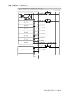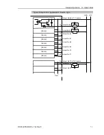
Setup & Operation 13. Option Slots
74
RC90 (EPSON RC+ 7.0) Rev.8
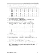
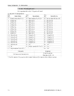
13.2.6 Pin Assignments
Pin Assignment table of the 1
st
Expansion I/O board.
Connector 1 Pin Assignments
Pin
No.
Signal Name
Pin
No.
Signal Name
Pin
No.
Signal Name
1
Input common No.64 to 71
18 Input common No.72 to 79
34 Input common No.80 to 87
2
Input No.64
19 Input No.72
35 Input No.80
3
Input No.65
20 Input No.73
36 Input No.81
4
Input No.66
21 Input No.74
37 Input No.82
5
Input No.67
22 Input No.75
38 Input No.83
6
Input No.68
23 Input No.76
39 Input No.84
7
Input No.69
24 Input No.77
40 Input No.85
8
Input No.70
25 Input No.78
41 Input No.86
9
Input No.71
26 Input No.79
42 Input No.87
10 Output No.64
27 Output No.70
43
Output No.75
11 Output No.65
28 Output No.71
44
Output No.76
12 Output No.66
29 Output No.72
45
Output No.77
13 Output No.67
30 Output No.73
46
Output No.78
14 Output No.68
31 Output No.74
47
Output No.79
15 Output No.69
32 NC
48
NC
16 NC
33 Output common No.72 to 79
49
NC
17 Output common No.64 to 71
50
NC
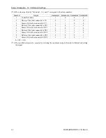
Connector
Standard
I/O Connector (Controller side)
D-sub 50 male pin
Mounting style #4 - 40
* The I/O connector, I/O connector cable, terminal block, and I/O connector kit are offered as options.
Summary of Contents for RC90
Page 1: ...Rev 8 EM158C3031F ROBOT CONTROLLER RC90 EPSON RC 7 0 ...
Page 2: ...ii ROBOT CONTROLLER RC90 EPSON RC 7 0 Rev 8 ...
Page 10: ...viii RC90 EPSON RC 7 0 Rev 8 ...
Page 17: ...Safety This section contains information for safety of the Robot System ...
Page 18: ......
Page 24: ......
Page 28: ...Setup Operation 1 Specifications 12 RC90 EPSON RC 7 0 Rev 8 1 3 Outer Dimensions Unit mm ...
Page 95: ...Maintenance This section contains maintenance procedures for the Robot Controller ...
Page 96: ......


