Setup & Operation 13. Option Slots
78
RC90 (EPSON RC+ 7.0) Rev.8
13.4.5 Communication Cable (RS-232C)
Prepare a communication cable as described in this section.
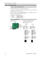
Connector
Standard
RS-232C
Connector
(Controller side)
D-sub 9 male pin
Mounting style #4 - 40
Use twisted pair cable for shielded wire.
Clamp the shield to the hood for noise prevention.
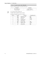
Pin assign of the RS-232C connector is as follows.
Pin No
Signal
Function
Signal Direction
1
DCD
Data carrier detect
Input
2
RXD
Receive data
Input
3
TXD
Send data
Output
4
DTR
Terminal ready
Output
5
GND
Signal ground
-
6
DSR
Data set ready
Input
7
RTS
Request to send
Output
8
CTS
Clear to send
Input
9
RI
Ring indicator
Input
NOTE
Summary of Contents for RC90
Page 1: ...Rev 8 EM158C3031F ROBOT CONTROLLER RC90 EPSON RC 7 0 ...
Page 2: ...ii ROBOT CONTROLLER RC90 EPSON RC 7 0 Rev 8 ...
Page 10: ...viii RC90 EPSON RC 7 0 Rev 8 ...
Page 17: ...Safety This section contains information for safety of the Robot System ...
Page 18: ......
Page 24: ......
Page 28: ...Setup Operation 1 Specifications 12 RC90 EPSON RC 7 0 Rev 8 1 3 Outer Dimensions Unit mm ...
Page 95: ...Maintenance This section contains maintenance procedures for the Robot Controller ...
Page 96: ......


