13 PWM & CAPTURE TIMER (T16E)
S1C17001 TECHNICAL MANUAL
EPSON
145
13.5 PWM & Capture Timer RUN/STOP Control
Set the following before starting the PWM & capture timer.
(1) Set the operating mode (input clock). See Section 13.2.
(2) Set the clock output. See Section 13.6.
(3) If using interrupts, set the interrupt level and permit interrupts for the PWM & capture timer. See Section 13.7.
(4) Set the counter value or reset to 0. See Section 13.3.
(5) Set the compare data. See Section 13.4.
The PWM & capture timer includes T16ERUN (D0/T16E_CTL register) to control Run/Stop.
∗
T16ERUN
: Timer Run/Stop Control Bit in the PWM Timer Control (T16E_CTL) Register (D0/0x5306)
The timer starts counting when T16ERUN is written as 1. Writing 0 to T16ERUN prevents clock input and stops
the count.
This control does not affect the counter data. The counter data is retained even when the count is halted, allowing
resumption of the count from that data.
If T16ERUN and T16ERST are written as 1 simultaneously, the timer starts counting after the reset.
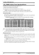
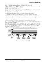
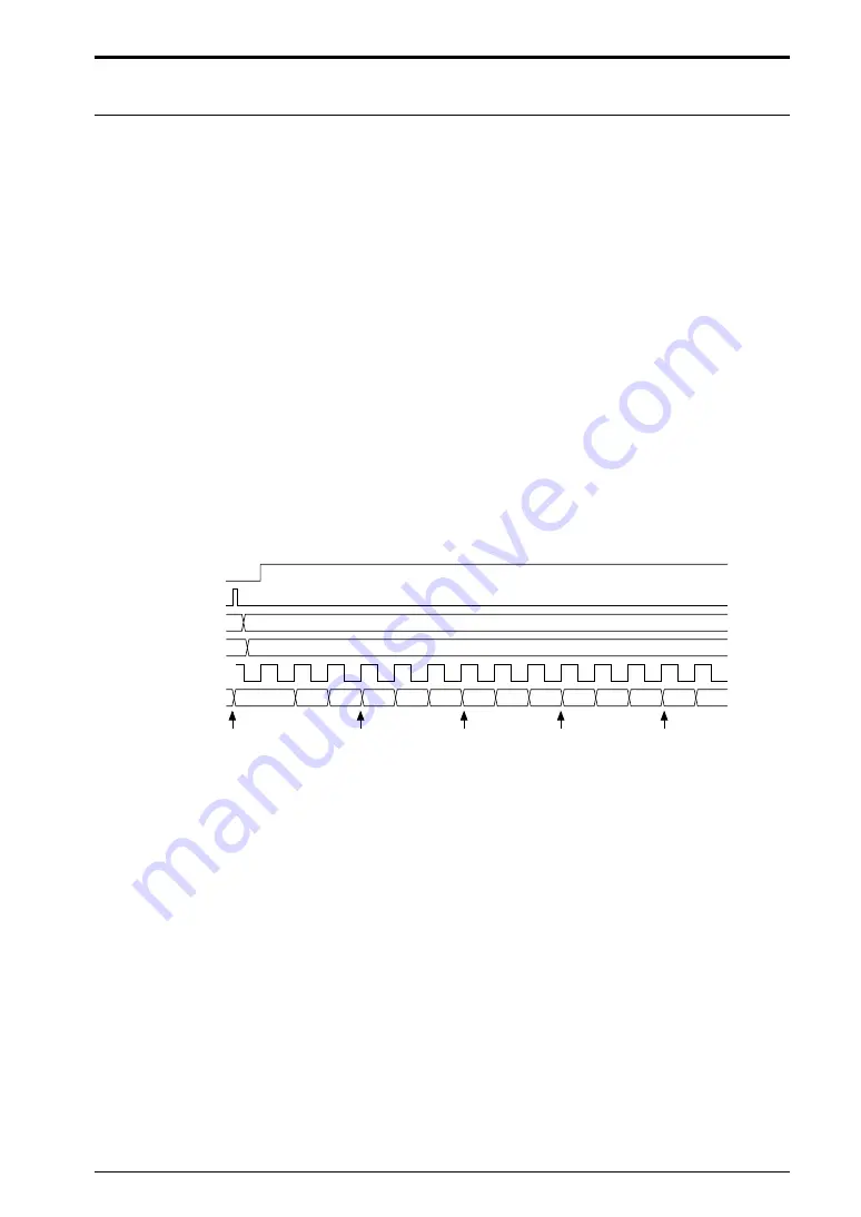
If the counter matches the compare data A register setting during counting, a compare A match signal is output and
a compare A interrupt factor generated.
Likewise, if the counter matches the compare data B register setting, a compare B match signal is output and a
compare B interrupt factor generated. The counter is reset to 0 at the same time. If CBUFEN is set to 1, the value
set in the compare data buffers is loaded into the compare data registers. If interrupts are permitted, an interrupt re-
quest is sent to the interrupt controller (ITC).
In either case, counting continues unaffected. For compare B, counting starts from the counter value 0.
T16ERUN
T16ERST
T16E_CA
T16E_CB
Input clock
T16E_TC
Reset
Compare A
interrupt
Reset and
compare B
interrupt
Compare A
interrupt
Reset and
compare B
interrupt
0x2
0
1
2
3
4
5
0
1
2
3
4
5
0
1
0x5
Figure 13.5.1: Basic counter operation timing
Summary of Contents for S1C17001
Page 1: ...Technical Manual S1C17001 CMOS 16 BIT SINGLE CHIP MICROCONTROLLER ...
Page 33: ...4 POWER SUPPLY VOLTAGE 24 EPSON S1C17001 TECHNICAL MANUAL This page intentionally left blank ...
Page 63: ...6 INITERRUPT CONTROLLER 54 EPSON S1C17001 TECHNICAL MANUAL This page intentionally left blank ...
Page 87: ...8 CLOCK GENERATOR CLG 78 EPSON S1C17001 TECHNICAL MANUAL This page intentionally left blank ...
Page 91: ...9 PRESCALER PSC 82 EPSON S1C17001 TECHNICAL MANUAL This page intentionally left blank ...
Page 133: ...11 16 BIT TIMER T16 124 EPSON S1C17001 TECHNICAL MANUAL This page intentionally left blank ...
Page 211: ...16 STOPWATCH TIMER SWT 202 EPSON S1C17001 TECHNICAL MANUAL This page intentionally left blank ...
Page 219: ...17 WATCHDOG TIMER WDT 210 EPSON S1C17001 TECHNICAL MANUAL This page intentionally left blank ...
Page 241: ...18 UART 232 EPSON S1C17001 TECHNICAL MANUAL This page intentionally left blank ...
Page 277: ...20 I2 C 268 EPSON S1C17001 TECHNICAL MANUAL This page intentionally left blank ...
Page 313: ...25 PACKAGE 304 EPSON S1C17001 TECHNICAL MANUAL This page intentionally left blank ...


