13 PWM & CAPTURE TIMER (T16E)
146
EPSON
S1C17001 TECHNICAL MANUAL
13.6 Clock Output Control
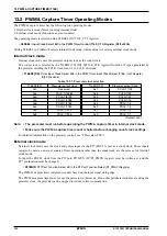
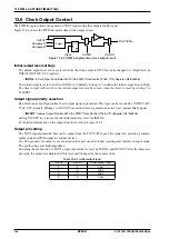
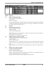
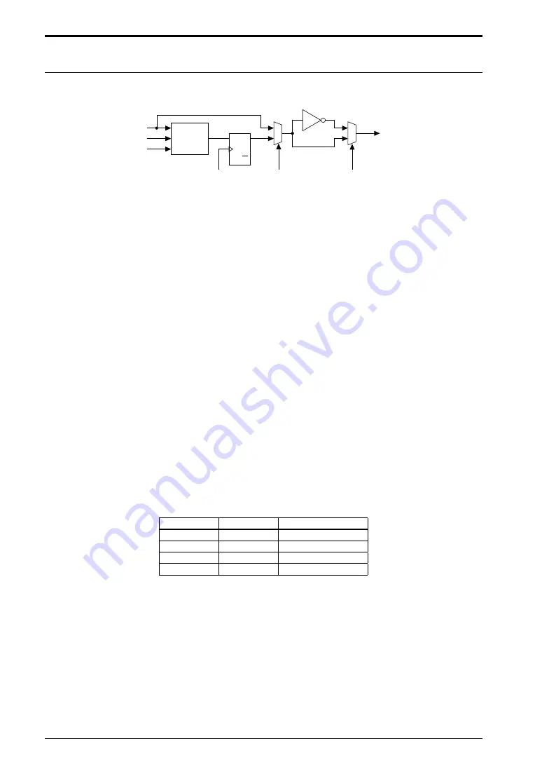
The PWM & capture timer can generate a TOUT signal using the compare match signal.
Figure 13.6.1 shows the PWM & capture timer clock output circuit.
Logic
INITOL
Compare A
Compare B
Clock
OUTEN
TOUT (P26)
INVOUT
D Q
Q
Figure 13.6.1: PWM & capture timer clock output circuit
Initial output level settings
The default output level is 0 (Low level) while the clock output is Off. This can be changed to 1 (High level) by
INITOL (D8/T16E_CTL register).
∗
INITOL
: Initial Output Level Select Bit in the PWM Timer Control (T16E_CTL) Register (D8/0x5306)
The initial output level is Low when INITOL is 0 (default). Setting to 1 switches the initial output level to High.
The timer output will switch to the initial output level set here even when the timer is reset by writing 1 to
T16ERST.
Output signal polarity selection
By default, an active High (normal Low) output signal is generated. This logic can be inverted by INVOUT (D4/
T16E_CTL register). Writing 1 to INVOUT causes the timer to generate an active Low (normal High) signal.
∗
INVOUT
: Inverse Output Control Bit in the PWM Timer Control (T16E_CTL) Register (D4/0x5306)
Setting INVOUT to 1 also inverts the initial output level set for INITOL.
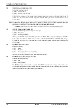
For detailed information on the output waveform, refer to Figure 13.6.2.
Output pin setting
The TOUT signal generated here can be output from the TOUT (P26) pin. This signal can provide a program-
mable clock and PWM signal to external devices.
The P26 pin used for output is set for input/output port use after initial resetting and switches to input mode.
The pin then becomes high-impedance.
Switching the pin function to TOUT output outputs the level set by INITOL and INVOUT. After the timer out-
put starts, the output is maintained at this level until changed by the counter value.
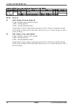
Table 13.6.1: Initial output level
INITOL
INVOUT
Initial output level
1
1
Low
1
0
High
0
1
High
0
0
Low
Summary of Contents for S1C17001
Page 1: ...Technical Manual S1C17001 CMOS 16 BIT SINGLE CHIP MICROCONTROLLER ...
Page 33: ...4 POWER SUPPLY VOLTAGE 24 EPSON S1C17001 TECHNICAL MANUAL This page intentionally left blank ...
Page 63: ...6 INITERRUPT CONTROLLER 54 EPSON S1C17001 TECHNICAL MANUAL This page intentionally left blank ...
Page 87: ...8 CLOCK GENERATOR CLG 78 EPSON S1C17001 TECHNICAL MANUAL This page intentionally left blank ...
Page 91: ...9 PRESCALER PSC 82 EPSON S1C17001 TECHNICAL MANUAL This page intentionally left blank ...
Page 133: ...11 16 BIT TIMER T16 124 EPSON S1C17001 TECHNICAL MANUAL This page intentionally left blank ...
Page 211: ...16 STOPWATCH TIMER SWT 202 EPSON S1C17001 TECHNICAL MANUAL This page intentionally left blank ...
Page 219: ...17 WATCHDOG TIMER WDT 210 EPSON S1C17001 TECHNICAL MANUAL This page intentionally left blank ...
Page 241: ...18 UART 232 EPSON S1C17001 TECHNICAL MANUAL This page intentionally left blank ...
Page 277: ...20 I2 C 268 EPSON S1C17001 TECHNICAL MANUAL This page intentionally left blank ...
Page 313: ...25 PACKAGE 304 EPSON S1C17001 TECHNICAL MANUAL This page intentionally left blank ...


