18 UART
218
EPSON
S1C17001 TECHNICAL MANUAL
18.6 Receive Errors
Three different receive errors may be detected while receiving data.
Since receive errors are interrupt factors, they can be processed by generating interrupts. For more information on
UART interrupt control, refer to Section 18.7.
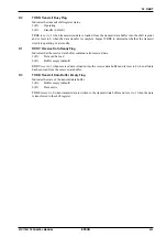
Parity error
If PREN (D3/UART_MOD register) has been set to 1 (parity enabled), data received is checked for parity.
Data received in the shift register is checked for parity when sent to the receive data buffer. The matching is
checked against the PMD (D2/UART_MOD register) setting (odd or even parity). If the result is a non-match, a
parity error is issued, and the parity error flag PER (D5/UART_ST register) is set to 1.
Even if this error occurs, the data received is sent to the receive data buffer, and the receiving operation contin-
ues. However, the received data cannot be guaranteed if a parity error occurs.
The PER flag (D5/UART_ST register) is reset to 0 by writing as 1.
∗
PREN
: Parity Enable Bit in the UART Mode (UART_MOD) Register (D3/0x4103)
∗
PMD
: Parity Mode Select Bit in the UART Mode (UART_MOD) Register (D2/0x4103)
∗
PER
: Parity Error Flag in the UART Status (UART_ST) Register (D5/0x4100)
Framing error
A framing error occurs if the stop bit is received as 0 and the UART determines sync offset. If the stop bit is set
to two bits, only the first bit is checked.
The framing error flag FER (D6/UART_ST register) is set to 1 if this error occurs. The received data is still
transferred to the receive data buffer if this error occurs and the receiving operation continues, but the data can-
not be guaranteed, even if no framing error occurs for subsequent data receiving.
The FER flag (D6/UART_ST register) is reset to 0 by writing as 1.
∗
FER
: Framing Error Flag in the UART Status (UART_ST) Register (D6/0x4100)
Overrun error
Even if the receive data buffer is full (two data items already received), a third item of data can be received in
the shift register. However, if the receive data buffer is not emptied (by reading out data received) by the time
this data has been received, the third item of data received in the shift register will not be sent to the buffer. A
fourth item of data sent in this state will overwrite the third item of data in the shift register and generate an
overrun error.
If an overrun error occurs, the overrun error flag OER (D4/UART_ST register) is set to 1.
The receiving operation continues even if this error occurs.
The OER flag (D4/UART_ST register) is reset to 0 by writing as 1.
∗
OER
: Overrun Error Flag in the UART Status (UART_ST) Register (D4/0x4100)
Summary of Contents for S1C17001
Page 1: ...Technical Manual S1C17001 CMOS 16 BIT SINGLE CHIP MICROCONTROLLER ...
Page 33: ...4 POWER SUPPLY VOLTAGE 24 EPSON S1C17001 TECHNICAL MANUAL This page intentionally left blank ...
Page 63: ...6 INITERRUPT CONTROLLER 54 EPSON S1C17001 TECHNICAL MANUAL This page intentionally left blank ...
Page 87: ...8 CLOCK GENERATOR CLG 78 EPSON S1C17001 TECHNICAL MANUAL This page intentionally left blank ...
Page 91: ...9 PRESCALER PSC 82 EPSON S1C17001 TECHNICAL MANUAL This page intentionally left blank ...
Page 133: ...11 16 BIT TIMER T16 124 EPSON S1C17001 TECHNICAL MANUAL This page intentionally left blank ...
Page 211: ...16 STOPWATCH TIMER SWT 202 EPSON S1C17001 TECHNICAL MANUAL This page intentionally left blank ...
Page 219: ...17 WATCHDOG TIMER WDT 210 EPSON S1C17001 TECHNICAL MANUAL This page intentionally left blank ...
Page 241: ...18 UART 232 EPSON S1C17001 TECHNICAL MANUAL This page intentionally left blank ...
Page 277: ...20 I2 C 268 EPSON S1C17001 TECHNICAL MANUAL This page intentionally left blank ...
Page 313: ...25 PACKAGE 304 EPSON S1C17001 TECHNICAL MANUAL This page intentionally left blank ...


