20 I
2
C
S1C17001 TECHNICAL MANUAL
EPSON
259
20.6 I
2
C Interrupts
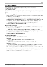
The I
2
C module includes a function for generating the following two different interrupt types.
• Transmit buffer empty interrupt
• Receive buffer full interrupt
The I
2
C module outputs one interrupt signal shared by the two above interrupt factor types to the interrupt control-
ler (ITC).
Transmit buffer empty interrupt
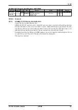
To use this interrupt, set TINTE (D0/I2C_ICTL register) to 1. If TINTE is set to 0 (default), interrupt requests
for this factor will not be sent to the ITC.
∗
TINTE
: Transmit Interrupt Enable Bit in the I
2
C Interrupt Control (I2C_ICTL) Register (D0/0x4346)
If transmit buffer empty interrupts are permitted (TINTE = 1), an interrupt request pulse is output to the ITC as
soon as the transmit data set in RTDT[7:0] (D[7:0]/I2C_DAT register) is transferred to the shift register.
∗
RTDT[7:0]
: Receive/Transmit Data Bits in the I
2
C Data (I2C_DAT) Register (D[7:0]/0x4344)
An interrupt occurs if other interrupt conditions are satisfied.
Receive buffer full interrupt
To use this interrupt, set RINTE (D1/I2C_ICTL register) to 1. If RINTE is set to 0 (default), interrupt requests
for this factor will not be sent to the ITC.
∗
RINTE
: Receive Interrupt Enable Bit in the I
2
C Interrupt Control (I2C_ICTL) Register (D1/0x4346)
If receive buffer full interrupts are permitted (RINTE = 1), an interrupt request pulse is output to the ITC as
soon as the data received in the shift register is loaded to RTDT[7:0].
An interrupt occurs if other interrupt conditions are met.
I
2
C interrupt ITC registers
The control bits for the I
2
C module in the ITC are listed below.
Interrupt
flag
∗
IIFT7
: I
2
C Interrupt Flag in the Interrupt Flag (ITC_IFLG) Register (D15/0x4300)
Interrupt enable bit
∗
IIEN7
: I
2
C Interrupt Enable Bit in the Interrupt Enable (ITC_EN) Register (D15/0x4302)
Interrupt level setting bit
∗
IILV7[2:0]
: I
2
C Interrupt Level Bits in the Internal Interrupt Level Setup (ITC_ILV3) Register 3 (D[10:8]/0x4314)
If an interrupt request pulse is output by the I
2
C module, the IIFT7 interrupt flag is set to 1.
If the IIEN7 interrupt enable bit is set to 1, the ITC sends an interrupt request to the S1C17 core. To prohibit
I
2
C interrupts, set IIEN7 to 0.
The IIFT7 flag is set to 1 by a I
2
C interrupt request pulse, regardless of the IIEN7 bit setting (i.e., even if set to 0).
The IILV7[2:0] interrupt level setting bit sets the I
2
C interrupt level (0 to 7).
Summary of Contents for S1C17001
Page 1: ...Technical Manual S1C17001 CMOS 16 BIT SINGLE CHIP MICROCONTROLLER ...
Page 33: ...4 POWER SUPPLY VOLTAGE 24 EPSON S1C17001 TECHNICAL MANUAL This page intentionally left blank ...
Page 63: ...6 INITERRUPT CONTROLLER 54 EPSON S1C17001 TECHNICAL MANUAL This page intentionally left blank ...
Page 87: ...8 CLOCK GENERATOR CLG 78 EPSON S1C17001 TECHNICAL MANUAL This page intentionally left blank ...
Page 91: ...9 PRESCALER PSC 82 EPSON S1C17001 TECHNICAL MANUAL This page intentionally left blank ...
Page 133: ...11 16 BIT TIMER T16 124 EPSON S1C17001 TECHNICAL MANUAL This page intentionally left blank ...
Page 211: ...16 STOPWATCH TIMER SWT 202 EPSON S1C17001 TECHNICAL MANUAL This page intentionally left blank ...
Page 219: ...17 WATCHDOG TIMER WDT 210 EPSON S1C17001 TECHNICAL MANUAL This page intentionally left blank ...
Page 241: ...18 UART 232 EPSON S1C17001 TECHNICAL MANUAL This page intentionally left blank ...
Page 277: ...20 I2 C 268 EPSON S1C17001 TECHNICAL MANUAL This page intentionally left blank ...
Page 313: ...25 PACKAGE 304 EPSON S1C17001 TECHNICAL MANUAL This page intentionally left blank ...

