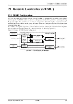
21 REMOTE CONTROLLER (REMC)
274
EPSON
S1C17001 TECHNICAL MANUAL
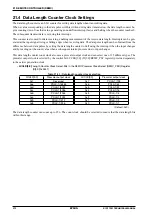
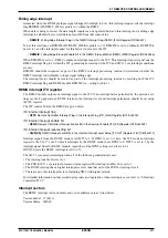
Given below are the values to which the data length counter is set:
Setting = Data pulse length (seconds) x prescaler output clock frequency (Hz)
The data length counter begins counting down from the value written using the prescaler output clock selected.
An underflow interrupt factor occurs when the data length counter value reaches 0. If interrupts are permitted,
an REMC interrupt request is output to the interrupt controller (ITC). The data length counter stops counting
when it reaches 0.
(5) Interrupt processing
To transmit the subsequent data, set the subsequent data (step 3) and set the data pulse length (step 4) as part of
the interrupt processing routine generated by the data length counter underflow.
(6) Data transmission end
To end data transmission, set REMEN to 0 after the final data transmission is complete (after underflow inter-
rupt has occurred).
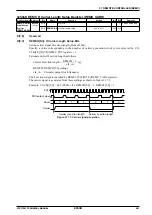
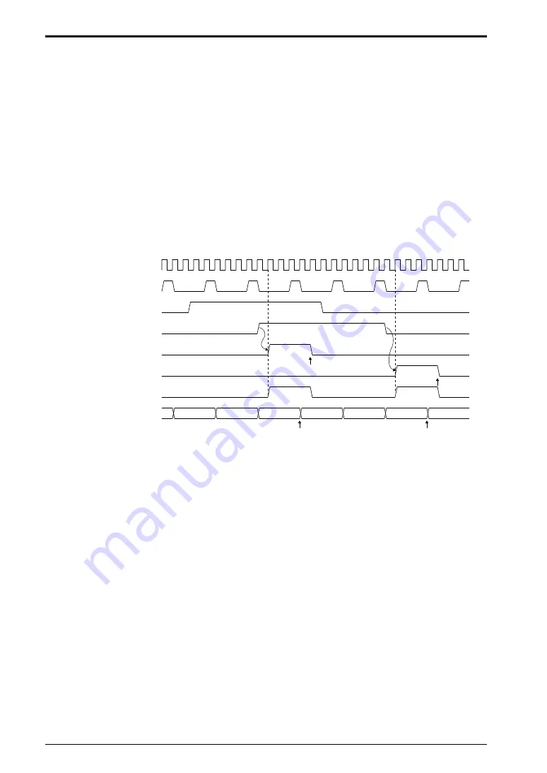
Data receipt control
PCLK
PSC output clock
(data length counter clock)
REMI input
REMDT
(sample waveform)
REMRIF
REMFIF
Interrupt signal
REMLEN[7:0]
0xff written
x+2
x+1
x
0xff
0xfe
0xfd
0xff
0xff written
1 written
1 written
Figure 21.5.3: Data receipt
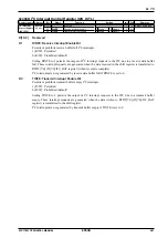
(1) Data receipt mode setting
Set REMC to receipt mode by writing 1 to REMMD (D1/REMC_CFG register).
(2) Permit data receipt
Permit REMC operation by setting REMEN (D0/REMC_CFG register) to 1. This initiates REMC transmission
(input edge detection operation).
.
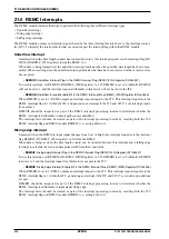
REMC detects input changes (signal rising or falling edges) by sampling the input signal from the REMI pin
using the prescaler output clock selected for carrier generation. If a signal edge is detected, a rising or falling
edge interrupt factor is generated. An REMC interrupt request is output to the ITC if interrupts are permitted.
Rising edge and falling edge interrupts can be individually permitted or blocked.
Note that if the signal level after the input has changed is not detected for at least two continuous sampling
clock cycles, the interrupt factor is interpreted as noise, and no rising or falling edge interrupt is generated.
Summary of Contents for S1C17001
Page 1: ...Technical Manual S1C17001 CMOS 16 BIT SINGLE CHIP MICROCONTROLLER ...
Page 33: ...4 POWER SUPPLY VOLTAGE 24 EPSON S1C17001 TECHNICAL MANUAL This page intentionally left blank ...
Page 63: ...6 INITERRUPT CONTROLLER 54 EPSON S1C17001 TECHNICAL MANUAL This page intentionally left blank ...
Page 87: ...8 CLOCK GENERATOR CLG 78 EPSON S1C17001 TECHNICAL MANUAL This page intentionally left blank ...
Page 91: ...9 PRESCALER PSC 82 EPSON S1C17001 TECHNICAL MANUAL This page intentionally left blank ...
Page 133: ...11 16 BIT TIMER T16 124 EPSON S1C17001 TECHNICAL MANUAL This page intentionally left blank ...
Page 211: ...16 STOPWATCH TIMER SWT 202 EPSON S1C17001 TECHNICAL MANUAL This page intentionally left blank ...
Page 219: ...17 WATCHDOG TIMER WDT 210 EPSON S1C17001 TECHNICAL MANUAL This page intentionally left blank ...
Page 241: ...18 UART 232 EPSON S1C17001 TECHNICAL MANUAL This page intentionally left blank ...
Page 277: ...20 I2 C 268 EPSON S1C17001 TECHNICAL MANUAL This page intentionally left blank ...
Page 313: ...25 PACKAGE 304 EPSON S1C17001 TECHNICAL MANUAL This page intentionally left blank ...


