6 INITERRUPT CONTROLLER
S1C17001 TECHNICAL MANUAL
EPSON
53
6.8 Precautions
• To prevent the recurrence of interrupts due to the same interrupt factor, always reset the interrupt flag before per-
mitting interrupts, resetting PSR, or executing the
reti
command.
• The S1C17001 interrupts listed below are in level trigger mode.
- P0 port interrupt
- P1 port interrupt
- Stopwatch timer interrupt
- Clock timer interrupt
- 8-bit OSC1 timer interrupt
- PWM & capture timer interrupt
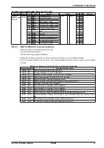
Make sure all EITG
x
bits within the ITC_ELV
x
registers (0x4306 to 0x430c) have been set to 1 (level trigger
mode).
The interrupt flag within peripheral modules must be reset (to 1) within the interrupt processing routine rather
than EIFT
x
. For more information on interrupt flags for resetting, refer to the peripheral module description.
Summary of Contents for S1C17001
Page 1: ...Technical Manual S1C17001 CMOS 16 BIT SINGLE CHIP MICROCONTROLLER ...
Page 33: ...4 POWER SUPPLY VOLTAGE 24 EPSON S1C17001 TECHNICAL MANUAL This page intentionally left blank ...
Page 63: ...6 INITERRUPT CONTROLLER 54 EPSON S1C17001 TECHNICAL MANUAL This page intentionally left blank ...
Page 87: ...8 CLOCK GENERATOR CLG 78 EPSON S1C17001 TECHNICAL MANUAL This page intentionally left blank ...
Page 91: ...9 PRESCALER PSC 82 EPSON S1C17001 TECHNICAL MANUAL This page intentionally left blank ...
Page 133: ...11 16 BIT TIMER T16 124 EPSON S1C17001 TECHNICAL MANUAL This page intentionally left blank ...
Page 211: ...16 STOPWATCH TIMER SWT 202 EPSON S1C17001 TECHNICAL MANUAL This page intentionally left blank ...
Page 219: ...17 WATCHDOG TIMER WDT 210 EPSON S1C17001 TECHNICAL MANUAL This page intentionally left blank ...
Page 241: ...18 UART 232 EPSON S1C17001 TECHNICAL MANUAL This page intentionally left blank ...
Page 277: ...20 I2 C 268 EPSON S1C17001 TECHNICAL MANUAL This page intentionally left blank ...
Page 313: ...25 PACKAGE 304 EPSON S1C17001 TECHNICAL MANUAL This page intentionally left blank ...

