10 INPUT/OUTPUT PORT (P)
90
EPSON
S1C17001 TECHNICAL MANUAL
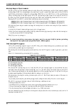
Interrupt flags in P port module
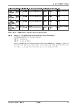
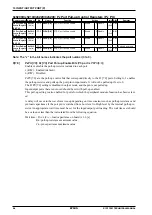
The ITC is able to accept interrupt requests for both P0 and P1 port interrupts, and the P port module contains
interrupt flags P
x
IF[7:0] corresponding to the individual 16 ports to enable individual control of the 16 P0[7:0]
and P1[7:0] port interrupts. Setting the corresponding P
x
IE[7:0] to 1 sets P
x
IF[7:0] to 1 at the specified edge
(rising or falling edge) of the input signal. A P0 or P1 port interrupt request signal is also output to the ITC at
the same time. This interrupt request signal causes the P0/P1 port interrupt flag inside the ITC to be set to 1.
Meeting the ITC and S1C17 core interrupt conditions generates an interrupt.
∗
P0IF[7:0]
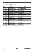
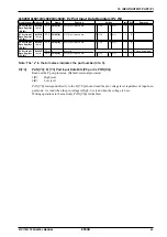
: P0[7:0] Port Interrupt Flags in the P0 Port Interrupt Flag (P0_IFLG) Register (D[7:0]/0x5207)
∗
P1IF[7:0]
: P1[7:0] Port Interrupt Flags in the P1 Port Interrupt Flag (P1_IFLG) Register (D[7:0]/0x5217)
The following processing is needed to manage the interrupt factor occurrence state using the P port module in-
terrupt flags.
1. Set the ITC P0 and P1 interrupt trigger mode to level trigger mode.
2. Reset the P port module interrupt flag P
x
IF[7:0] within the interrupt processing routine after the interrupt oc-
curs (this also resets the ITC interrupt flag).
P
x
IF[7:0] is reset by writing as 1.
Note: To prevent generating unnecessary interrupts, reset the relevant P
x
IF[7:0] before permitting
interrupts for the required port using P
x
IE[7:0] (P
x
_IMSK register).
Port interrupt ITC register
A P0 or P1 port interrupt signal is output to the ITC if the port for which interrupts are permitted as previously
set detects the specified edge of an input signal.
The interrupt level and interrupt permission should be set for the ITC register in order to generate a port inter-
rupt.
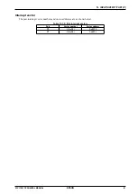
Table 10.7.1 illustrates the port interrupt ITC control bits.
Table 10.7.1: ITC control bits
Port
Interrupt flag
Interrupt enable
Interrupt level setting
Trigger mode setting
P0
EIFT0 (D0/ITC_IFLG)
EIEN0 (D0/ITC_EN)
EILV0[2:0] (D[2:0]/ITC_ELV0)
EITG0 (D4/ITC_ELV0)
P1
EIFT1 (D1/ITC_IFLG)
EIEN1 (D1/ITC_EN)
EILV1[2:0] (D[10:8]/ITC_ELV0)
EITG1 (D12/ITC_ELV0)
ITC_IFLG register (0x4300)
ITC_EN register (0x4302)
ITC_ELV0 register (0x4306)
The relevant ITC interrupt flag is set to 1 when the P0 or P1 port interrupt signal is activated. When the inter-
rupt enable bit corresponding to that interrupt flag is set to 1, the ITC sends an interrupt request to the S1C17
core. To block port interrupts, set the interrupt enable bit to 0. The interrupt flag is set to 1 by the P0 or P1 port
interrupt signal regardless of the interrupt enable bit setting (even if set to 0).
The interrupt level setting bit sets the port interrupt level (0 to 7). The P0 port takes precedence if the same in-
terrupt level is set.
As previously mentioned, the port interrupt trigger mode setting bit must always be set to 1 (level trigger).
The S1C17 core accepts interrupts when all of the following conditions are met:
• Interrupt enable bit is set to 1
• The PSR (S1C17 core internal processor status register) IE (interrupt enable) bit is set to 1.
• The port interrupt has a higher set interrupt level than the PSR IL (interrupt level).
• No other interrupt factors having higher precedence (e.g., NMI) are present.
For more information on these interrupt control registers and procedures for when an interrupt occurs, refer to “6
Interrupt Controller (ITC).”
Summary of Contents for S1C17001
Page 1: ...Technical Manual S1C17001 CMOS 16 BIT SINGLE CHIP MICROCONTROLLER ...
Page 33: ...4 POWER SUPPLY VOLTAGE 24 EPSON S1C17001 TECHNICAL MANUAL This page intentionally left blank ...
Page 63: ...6 INITERRUPT CONTROLLER 54 EPSON S1C17001 TECHNICAL MANUAL This page intentionally left blank ...
Page 87: ...8 CLOCK GENERATOR CLG 78 EPSON S1C17001 TECHNICAL MANUAL This page intentionally left blank ...
Page 91: ...9 PRESCALER PSC 82 EPSON S1C17001 TECHNICAL MANUAL This page intentionally left blank ...
Page 133: ...11 16 BIT TIMER T16 124 EPSON S1C17001 TECHNICAL MANUAL This page intentionally left blank ...
Page 211: ...16 STOPWATCH TIMER SWT 202 EPSON S1C17001 TECHNICAL MANUAL This page intentionally left blank ...
Page 219: ...17 WATCHDOG TIMER WDT 210 EPSON S1C17001 TECHNICAL MANUAL This page intentionally left blank ...
Page 241: ...18 UART 232 EPSON S1C17001 TECHNICAL MANUAL This page intentionally left blank ...
Page 277: ...20 I2 C 268 EPSON S1C17001 TECHNICAL MANUAL This page intentionally left blank ...
Page 313: ...25 PACKAGE 304 EPSON S1C17001 TECHNICAL MANUAL This page intentionally left blank ...

